The Challenge of Unmarked Automotive Wiring
Working on a vehicle's electrical system often involves tracing harnesses that have been exposed to decades of heat cycles, chemical exposure, and physical abrasion. A common frustration for both novice DIYers and seasoned technicians is discovering a damaged wire with no printed specifications on the insulation. If you are wondering how to determine wire gauge if not marked, you must rely on physical measurement and circuit deduction rather than guesswork. Guessing the American Wire Gauge (AWG) size can lead to catastrophic voltage drop, melted insulation, or an electrical fire, especially in high-amperage circuits like cooling fan relays or fuel pump feeds.
The Thin-Wall Insulation Trap: Why You Cannot Measure the Outside
The most critical mistake beginners make when trying to identify automotive wire is measuring the outside diameter of the insulation. Standard household wiring (like THHN or Romex) uses thick insulation, and many generic wire gauge wheels are calibrated for these building wires. However, modern automotive harnesses primarily use SAE J1128 standard thin-wall wires, such as GXL (General Cross-Linked) or TXL (Thin Cross-Linked). These wires feature a much thinner, harder polyvinyl chloride (PVC) or cross-linked polyethylene (XLPE) jacket designed to save weight and fit into tight looms. Because the insulation is significantly thinner than standard building wire, measuring the outside diameter will yield a falsely small gauge reading, leading you to overestimate the wire's current-carrying capacity.
To accurately determine the gauge, you must strip away the insulation and measure the bare copper conductor bundle or use circuit deduction logic.
Method 1: Measuring Copper Diameter with Digital Calipers
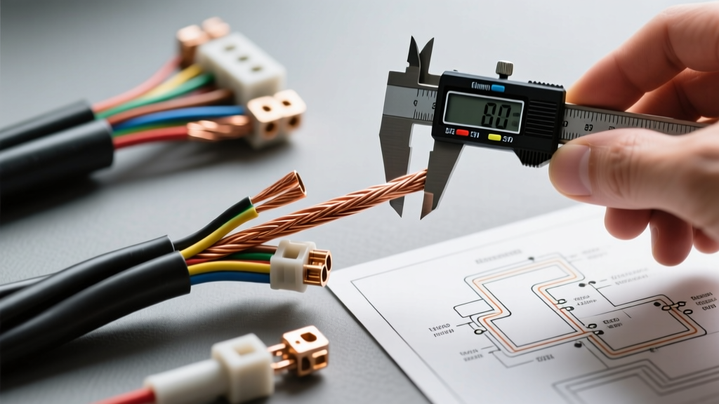
The most reliable way to find the AWG of an unmarked wire is by measuring the bare copper diameter using a precision digital caliper (such as a Mitutoyo or Neiko digital caliper). This method requires a small section of exposed wire.
Step-by-Step Caliper Measurement
- Strip the Insulation: Use a high-quality wire stripper (like the Klein Tools 11063W) to carefully remove exactly 1/2 inch of insulation from the end of the wire. Do not nick or scrape the copper strands, as this alters the diameter.
- Twist the Strands Tightly: Automotive wire is stranded for flexibility. Gently but firmly twist the exposed copper strands together so they form a tight, uniform cylinder without any flaring at the tip.
- Measure the Bundle: Open the digital caliper and place the twisted copper bundle between the lower outside measurement jaws. Close the jaws gently. Warning: Do not compress the copper. You want to measure the natural resting diameter of the bundle.
- Read the Measurement: Switch the caliper to inches (IN). Compare your reading to an AWG reference chart (provided below).
Method 2: The Single-Strand Calculation Method
If the wire is heavily corroded, frayed, or you cannot get a clean bundle measurement, you can calculate the gauge by measuring a single strand. This requires a micrometer or a high-quality caliper capable of measuring to the ten-thousandth of an inch.
- Isolate a single copper strand from the wire bundle and snip it off.
- Measure the diameter of this single strand in inches.
- Count the total number of strands in the wire bundle.
- Use the Circular Mil (CM) formula: CM = (Diameter of one strand in mils)^2 x Total number of strands. (Note: 1 mil = 0.001 inches).
- Cross-reference the total Circular Mils with an AWG chart to find your gauge.
For example, if you measure a single strand at 0.0113 inches (11.3 mils) and count 19 strands, the calculation is (11.3)^2 x 19 = 2,424 CM. This closely aligns with standard 16 AWG wire.
Method 3: Circuit Deduction and Color Code Analysis
When physical measurement is impossible—such as when a wire is broken flush against a connector pin—you must use circuit deduction. Automotive engineers design harnesses based on specific amperage loads. By identifying what the wire connects to, and cross-referencing standard OEM color codes, you can confidently deduce the gauge.
Common Automotive Circuit Gauges and OEM Colors
| Circuit Function | Typical AWG Size | Expected Amperage Load | Common OEM Color Examples (GM/Ford) |
|---|---|---|---|
| ECU Sensors (MAF, TPS, O2 Signal) | 18 to 20 AWG | Less than 2 Amps | Black, Yellow, Light Blue (Signal wires) |
| O2 Sensor Heater Feed | 14 to 16 AWG | 4 to 8 Amps | Pink (GM), Dark Blue (Ford) |
| Headlights / High Beams | 12 to 14 AWG | 10 to 15 Amps | Tan (GM Low Beam), Light Green (High Beam) |
| Fuel Pump Feed | 10 to 12 AWG | 12 to 20 Amps | Grey or Purple (GM), Pink/Black (Ford) |
| Alternator Main Output | 4 to 8 AWG | 80 to 150+ Amps | Red with fusible link, or heavy Black |
| Starter Motor Solenoid Feed | 2 to 4 AWG | 200+ Amps (Cranking) | Heavy Red or Purple |
Expert Insight: If you are repairing a GM Gen III/IV LS engine harness and find an unmarked thin black wire leading to a sensor ground, it is almost certainly 18 AWG. If you find a thicker pink wire near the O2 sensor, it is the 16 AWG heater circuit. Using 18 AWG for the heater circuit will result in severe voltage drop, causing the O2 sensor to fail to reach operating temperature and triggering a P0031 or P0051 diagnostic trouble code.
SAE J1128 Automotive Wire Reference Chart
The following chart outlines the nominal bare copper diameters for standard automotive thin-wall (GXL/TXL) wire. Use this chart in conjunction with your digital caliper measurements. For more detailed specifications on cross-linked automotive wire standards, refer to the SAE J1128 Standard documentation.
| AWG Size | Nominal Copper Diameter (Inches) | Nominal Copper Diameter (mm) | Typical Strand Count (GXL) | Max Ampacity (Chassis Wiring) |
|---|---|---|---|---|
| 8 AWG | 0.1433' | 3.64 mm | 133 | 70 Amps |
| 10 AWG | 0.1137' | 2.89 mm | 84 | 50 Amps |
| 12 AWG | 0.0902' | 2.29 mm | 53 | 35 Amps |
| 14 AWG | 0.0715' | 1.82 mm | 41 | 25 Amps |
| 16 AWG | 0.0567' | 1.44 mm | 26 | 15 Amps |
| 18 AWG | 0.0450' | 1.14 mm | 19 | 10 Amps |
| 20 AWG | 0.0357' | 0.91 mm | 19 | 7 Amps |
Note: Ampacity ratings are for single wires in free air (chassis wiring) at an ambient temperature of 20°C (68°F). Wires bundled tightly inside a harness loom under the hood will experience thermal derating and should be upsized by one gauge for safety. For further technical data on conductor sizing, consult the Allied Wire & Cable AWG Conductor Sizing Guide.
Troubleshooting Voltage Drop Caused by Incorrect Gauge Assumptions
Why does getting the gauge right matter so much? If you assume an unmarked wire is 12 AWG when it is actually 14 AWG, and you use it to power a 15-amp accessory like an auxiliary light bar, the wire will operate beyond its safe thermal limit. Over time, the copper will anneal (soften) due to heat, increasing its electrical resistance. This creates a voltage drop.
The 3% Voltage Drop Rule
In automotive 12-volt systems, a voltage drop of more than 3% (0.36 volts) across a power circuit is considered unacceptable. If you are troubleshooting an existing circuit where the wire gauge is unknown and the component is underperforming (e.g., dim headlights or a slow power window motor), perform a voltage drop test before replacing the component.
- Set your digital multimeter to DC Volts.
- Connect the red probe to the positive battery terminal and the black probe to the component's power input pin.
- Activate the circuit.
- If the meter reads more than 0.36V, the wire is either too small (incorrect gauge), excessively long, or suffering from internal corrosion.
Summary: Best Practices for the Bench and the Bay
Knowing how to determine wire gauge if not marked is a foundational skill for automotive electrical diagnostics. Always default to measuring the bare copper with digital calipers and referencing SAE J1128 thin-wall specifications. When physical measurement is impossible, use circuit deduction based on the component's amperage draw and OEM color coding. Finally, keep a set of known-gauge pigtails (10, 12, 14, 16, and 18 AWG) in your toolbox. Visually and physically comparing the unmarked wire against a known standard is often the fastest way to confirm your caliper measurements in a cramped engine bay.