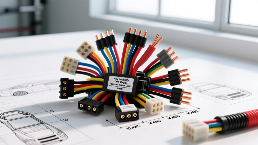
The Critical Role of Correct AWG Sizing in Vehicle Electrical Systems
Upgrading a vehicle's electrical system, whether for a high-output alternator, a modern EFI conversion, or a high-flow fuel pump, requires precise wire selection. Guessing the American Wire Gauge (AWG) or relying on visual estimates of insulated wire frequently leads to catastrophic voltage drops, melted harnesses, and intermittent component failure. Understanding how to identify wire gauge accurately and selecting the correct automotive-grade cable is the foundation of reliable 12-volt and 14-volt system design. This guide provides a comprehensive product comparison and selection methodology for automotive wiring, grounded in SAE standards and real-world chassis integration.
How to Identify Wire Gauge on Existing Harnesses
When repairing or modifying an existing wiring harness, the jacket print is often degraded by engine oil, heat, and abrasion. To determine the exact AWG, you must strip a small section of the insulation and measure the bare copper conductor. Do not measure the insulated diameter, as insulation thickness varies wildly between wire types (e.g., GPT vs. TXL).
Using Digital Calipers and the SAE J1128 Standard
According to the SAE J1128 standard for low-tension primary cable, wire gauge is defined by the cross-sectional area and bare copper diameter of the conductor, not the overall thickness of the wire. Using a calibrated digital caliper, measure the bare copper strand bundle. Compare your measurement to the standard bare copper diameters below:
| AWG Size | Bare Copper Diameter (mm) | Bare Copper Diameter (inches) | Strand Count (Typical) |
|---|---|---|---|
| 8 AWG | 3.264 mm | 0.1285" | 133 |
| 10 AWG | 2.588 mm | 0.1019" | 105 |
| 12 AWG | 2.053 mm | 0.0808" | 65 |
| 14 AWG | 1.628 mm | 0.0641" | 41 |
| 16 AWG | 1.291 mm | 0.0508" | 26 |
| 18 AWG | 1.024 mm | 0.0403" | 16 |
Pro-Tip: If the wire is heavily oxidized or tinned, lightly scrape the outer layer of the copper strands before measuring to ensure an accurate reading. Tinning adds a microscopic layer of solder that can skew caliper readings by up to 0.05mm, pushing a 12 AWG wire into the 10 AWG measurement range.
Automotive Wire Types: GPT, HDT, and TXL Compared
Once you know how to identify wire gauge, the next step in the selection process is choosing the correct insulation type. Standard hardware store THHN or stranded copper wire is not suitable for automotive environments due to its inability to withstand constant vibration, extreme thermal cycling, and exposure to hydrocarbons.
| Wire Type | Insulation Material | Wall Thickness | Max Temp Rating | Best Application |
|---|---|---|---|---|
| GPT | PVC (Thermoplastic) | Standard | 105°C (221°F) | General chassis wiring, interior harnesses, lighting circuits. |
| HDT | PVC (Thermoplastic) | Heavy Duty | 105°C (221°F) | High-abrasion areas, battery cables, engine bay routing near moving parts. |
| TXL | Cross-Linked Polyethylene (XLPE) | Thin Wall | 125°C (257°F) | Tight engine bays, EFI harnesses, high-heat zones near exhaust manifolds. |
For modern high-performance builds, TXL is the superior choice. Its cross-linked polyethylene insulation allows for a much thinner wall than GPT while offering higher heat resistance and superior abrasion protection. A 10 AWG TXL wire will have a smaller overall diameter than a 10 AWG GPT wire, making it significantly easier to pull through factory firewall grommets and loom.
Ampacity and Voltage Drop: Selecting the Right Gauge
Identifying the gauge is only half the battle; selecting the correct gauge for the load is where most electrical failures occur. Automotive systems operate on a nominal 12V to 14.4V spectrum. At these low voltages, current (amperage) must increase to deliver the same wattage, making the system highly susceptible to voltage drop.
As noted in Painless Performance's wiring manuals, a voltage drop of just 1.5 volts across a fuel pump circuit can reduce pump output by 20% or more, leading to lean conditions under boost. The formula for voltage drop is V = I × R (Voltage = Current × Resistance). Because resistance increases with wire length and decreases with wire thickness, longer harness runs require stepping up the wire gauge.
| AWG Size | Max Amps (Chassis Wiring)* | Resistance per 10ft (Ohms) | Voltage Drop at 15A (10ft run) |
|---|---|---|---|
| 8 AWG | 50A - 70A | 0.0062 Ω | 0.09V |
| 10 AWG | 30A - 40A | 0.0099 Ω | 0.15V |
| 12 AWG | 20A - 25A | 0.0158 Ω | 0.24V |
| 14 AWG | 15A - 20A | 0.0252 Ω | 0.38V |
| 16 AWG | 10A - 13A | 0.0401 Ω | 0.60V |
| 18 AWG | 7A - 10A | 0.0638 Ω | 0.96V |
*Note: Chassis wiring ampacity ratings assume single wires in free air or loosely bundled. Tightly bundled harnesses inside conduit require derating by up to 20% due to trapped heat.
Real-World Application: Upgrading a High-Flow Fuel Pump Circuit
To demonstrate the selection guide in action, let's examine a common upgrade: installing a Walbro 450lph fuel pump in a boosted application. This pump can draw up to 18 amps continuously at 60 PSI, with an initial startup spike exceeding 22 amps. Using standard 14 AWG wire and a factory 15A relay will result in severe voltage drop, relay overheating, and potential pump failure.
Component and Wire Selection
- Main Power Feed (Battery to Relay): 10 AWG TXL (Red). The short run from the battery positive to the relay Pin 30 requires 10 AWG to handle the 22A spike without heating up. Protected by a 30A MAXI fuse.
- Relay to Pump Feed: 10 AWG TXL (Red). The run from the relay Pin 87 to the fuel pump hanger is often 12 to 15 feet. 10 AWG ensures the voltage drop remains under 0.25V.
- Ground Circuit: 10 AWG TXL (Black). The ground path is just as critical as the power path. Ground the pump directly to a clean, bare-metal chassis point using a 10 AWG ring terminal, not through a factory daisy-chain ground.
- Trigger Circuit: 18 AWG GPT (Blue). The trigger wire from the ECU or ignition switch to the relay Pin 86 draws less than 0.5A, making 18 AWG perfectly adequate.
Relay Pinout and Termination
Utilize a heavy-duty Bosch-style 5-pin relay (using only 4 pins). The standard ISO mini relay pinout is:
- Pin 30: 12V+ Constant from Battery (10 AWG)
- Pin 87: 12V+ Out to Fuel Pump (10 AWG)
- Pin 85: Ground (14 AWG)
- Pin 86: 12V+ Trigger from ECU/Ignition (18 AWG)
Common Mistakes When Identifying and Selecting Wire
- Confusing SWG with AWG: Standard Wire Gauge (SWG), often used in British automotive applications, differs slightly from AWG. Always verify you are using an AWG stripping tool or caliper chart.
- Ignoring the Ground Path: Upgrading the positive feed to 8 AWG while leaving the factory 16 AWG ground wire intact creates a bottleneck. The circuit is only as robust as its smallest gauge wire.
- Using CCA (Copper Clad Aluminum): Never use CCA wire in automotive applications. It has higher resistance than pure copper, is highly susceptible to galvanic corrosion when crimped with copper terminals, and lacks the tensile strength to survive engine bay vibrations.
Summary
Knowing how to identify wire gauge by measuring bare copper diameter and understanding the differences between GPT, HDT, and TXL insulation are critical skills for any automotive electrician. By referencing SAE J1128 standards, calculating voltage drop over your specific harness length, and utilizing proper open-barrel crimping techniques, you can build a vehicle electrical system that is safe, efficient, and capable of supporting modern high-draw accessories.