Understanding the Smallest Gauge Wire in Automotive Systems
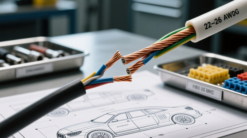
When automotive technicians and advanced DIYers refer to the smallest gauge wire in a modern vehicle’s harness, they are typically discussing 22 AWG down to 26 AWG conductors. Unlike the heavy 8 AWG or 4 AWG cables used for starter motors, high-amperage charging circuits, or electric power steering racks, these micro-wires are strictly dedicated to low-current signal transmission and data networking. You will find the smallest gauge wire routing critical data between the Engine Control Unit (ECU), Transmission Control Module (TCM), and highly sensitive sensors like the Mass Air Flow (MAF), Throttle Position Sensor (TPS), and wideband Oxygen (O2) sensors.
Working with these delicate conductors requires a complete departure from standard automotive crimping techniques. Attempting to use a standard vinyl butt connector and a heavy-duty ratcheting crimping tool on a 24 AWG wire will crush the copper strands, severing the conductor inside the insulation. This leads to immediate signal degradation, high resistance, voltage drops, and inevitable diagnostic trouble codes (DTCs) such as P0131 (O2 Sensor Circuit Low Voltage) or U0100 (Lost Communication with ECM/PCM). To properly install and repair the smallest gauge wire, technicians must adhere to strict micro-splicing protocols, often borrowing techniques from aerospace wiring standards like NASA-STD-8739.4, which dictates precise crimp and splice methodologies for delicate conductors.
Technical Specifications: 22 to 26 AWG Reference Chart
The following chart outlines the physical and electrical characteristics of the smallest gauge wires commonly found in automotive harnesses, based on standard copper conductivity and SAE J1128 low-tension primary cable specifications.
| AWG Size | Diameter (mm) | Resistance (Ohms/1000ft) | Max Ampacity (Chassis) | Primary Automotive Application |
|---|---|---|---|---|
| 20 AWG | 0.812 | 10.15 | 5.0 Amps | Ignition coil signals, injector low-side drivers |
| 22 AWG | 0.643 | 16.14 | 3.0 Amps | CAN Bus networks (High/Low), MAF sensor signals |
| 24 AWG | 0.510 | 25.67 | 2.0 Amps | Wideband O2 sensor reference cells, LIN bus data |
| 26 AWG | 0.404 | 40.81 | 1.0 Amps | Thermocouple extensions, micro-sensor shielding |
Required Tooling for Micro-Wire Installation
Standard electrical tools will destroy the smallest gauge wire. To ensure a reliable, low-resistance connection that withstands the harsh under-hood environment, you must utilize specialized micro-tooling:
- Precision Wire Strippers: Use strippers specifically calibrated for 22-30 AWG, such as the Engineer PA-20 or Irwin Vise-Grip micro-strippers. Standard automatic strippers often nick the copper core of 24 AWG wire, reducing its tensile strength by up to 60%.
- Rosin-Core Solder (63/37 Eutectic): A fine 0.031-inch diameter rosin-core solder is mandatory for wicking into the micro-strands without creating a bulky, brittle joint.
- No-Clean Flux Pen: Essential for promoting capillary action during soldering, especially on older harness wires that have experienced minor surface oxidation.
- Dual-Wall Adhesive Heat Shrink: Standard thin-wall heat shrink will not provide environmental sealing. You must use 3M or Raychem dual-wall (adhesive-lined) heat shrink with a 3:1 or 4:1 shrink ratio to create a waterproof seal over the micro-splice.
- Temperature-Controlled Soldering Station: Set to 350°C (662°F). High-wattage, unregulated soldering irons will instantly melt the thin PVC or cross-linked polyethylene (XLPE) insulation used on modern automotive wires.
Step-by-Step Installation: Splicing 22 AWG Sensor Wiring
When repairing a broken 22 AWG signal wire, mechanical strength and electrical conductivity are equally critical. The following procedure outlines the industry-standard modified Western Union splice, adapted for automotive micro-wires.
Step 1: Precision Stripping and Preparation
Strip exactly 3/4 inch (19mm) of insulation from both wire ends. Inspect the copper strands under a magnifying lamp. If even a single strand is nicked or cut by the stripping tool, cut the wire back and start over. A nicked strand will create a stress riser, leading to a fatigue failure under engine vibration. Slide a piece of dual-wall adhesive heat shrink onto one side of the wire before proceeding.
Step 2: The Modified Western Union Splice
Cross the two stripped ends to form an 'X' about 1/4 inch from the insulation. Twist the wires around each other tightly, making at least four complete wraps on each side. This mechanical interlock ensures that the splice will not pull apart under tension, taking the physical stress off the solder joint. Trim any sharp, protruding wire ends flush with flush-cutting micro-shears to prevent them from piercing the heat shrink later.
Step 3: Flux Application and Soldering
Apply a light coat of no-clean flux to the twisted joint. Touch the tip of your temperature-controlled iron to the bottom of the splice, and feed the 0.031-inch solder to the top of the joint. Allow capillary action to draw the molten solder completely through the twisted strands. The joint should appear shiny and smooth. A dull, grainy appearance indicates a cold solder joint, which will introduce erratic resistance into the sensor circuit.
Step 4: Environmental Sealing
Slide the dual-wall adhesive heat shrink over the soldered joint, ensuring it overlaps the original wire insulation by at least 1/2 inch on both sides. Apply heat evenly using a dedicated heat gun (not a lighter or torch). Watch for the adhesive to melt and squeeze out of both ends of the tubing, indicating a complete waterproof seal. This prevents moisture ingress and subsequent copper corrosion, which is the leading cause of high-resistance DTCs in sensor circuits.
Real-World Application: GM GMLAN / CAN Bus Network Repair
The most critical application of the smallest gauge wire in modern vehicles is the Controller Area Network (CAN) bus. On General Motors vehicles utilizing the GMLAN architecture, the high-speed CAN network relies on a twisted pair of 22 AWG wires to transmit data at up to 500 kbps between the ECM, TCM, and Body Control Module (BCM).
When diagnosing a U-code (network communication fault), you may find a break in this 22 AWG twisted pair. According to the Bosch Automotive Handbook, the physical geometry of a CAN bus twisted pair is vital for rejecting electromagnetic interference (EMI). The wires must be twisted at a rate of approximately one twist per inch (25mm).
Repair Protocol for GM CAN Bus (OBD-II DLC Pins 6 and 14):
- Identify the Wires: CAN High is typically Dark Green (Pin 6 at the DLC), and CAN Low is Dark Blue (Pin 14). Both are 22 AWG.
- Untwist and Splice: Untwist the harness no more than 2 inches from the break point. Perform the modified Western Union splice and solder as detailed above on each individual wire.
- Restore the Twist: Once both wires are soldered and individually heat-shrunk, you must re-twist the pair together at the original factory pitch (approx. 1 twist per inch). Failure to restore the twist will alter the characteristic impedance of the cable (nominally 120 ohms), causing signal reflection and network dropouts.
- Shielding: If the original harness featured a braided drain wire or foil shield, it must be reconnected and grounded to maintain the network's immunity to alternator whine and ignition coil EMI.
Common Failure Modes and Troubleshooting Decision Tree
When working with the smallest gauge wire, improper installation techniques manifest in specific, diagnosable ways. Use this troubleshooting matrix to identify installation errors:
| Symptom / DTC | Probable Installation Error | Corrective Action |
|---|---|---|
| Intermittent Signal Drop / P0101 (MAF Performance) | Nicked copper strands during stripping causing fatigue break under vibration. | Cut back wire, inspect strands under magnification, and re-splice using precision micro-strippers. |
| High Resistance / U0100 (Lost Comm) | Cold solder joint or excessive rosin flux residue trapping air in the splice. | Remove heat shrink, re-flux, and reflow solder at 350°C until capillary wicking is visible. |
| Network Noise / Multiple Module U-Codes | CAN Bus twisted pair untwisted or replaced with non-twisted 22 AWG wire. | Replace splice section with factory-spec twisted pair cable; maintain 1-twist-per-inch geometry. |
| Corrosion / Green Crust at Splice | Use of single-wall heat shrink or failure to achieve adhesive melt-out. | Strip old shrink, clean with isopropyl alcohol, and apply 3:1 dual-wall adhesive heat shrink. |
Mastering the installation of the smallest gauge wire separates amateur wiring jobs from professional, dealership-level repairs. By respecting the physical limitations of 22-26 AWG conductors and utilizing aerospace-grade splicing techniques, you ensure that critical ECU data remains intact, preserving the drivability and reliability of modern automotive electrical systems.