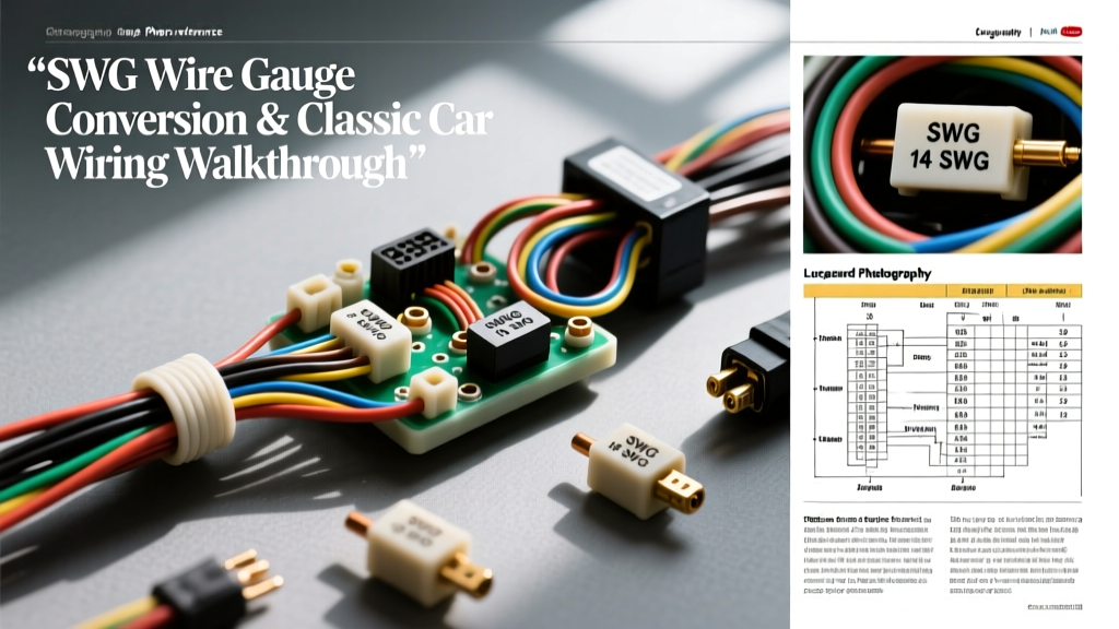
Understanding SWG Wire Gauge in Classic Automotive Systems
When restoring, modifying, or troubleshooting classic British vehicles—such as the MGB, Triumph TR6, Jaguar E-Type, or early Land Rover models—encountering the SWG wire gauge (Standard Wire Gauge) system is inevitable. Also known as Imperial Wire Gauge (IWG) or British Standard Wire Gauge, SWG was the foundational standard for electrical wiring in the UK before the global adoption of the metric system and the American Wire Gauge (AWG). For modern technicians and DIY restorers, misinterpreting an SWG wire gauge specification on a vintage wiring diagram can lead to severe voltage drops, melted insulation, or catastrophic electrical fires.
The primary confusion arises because SWG and AWG scale inversely in certain size ranges, and a direct 1:1 numerical match does not mean the wires are physically identical. For instance, an SWG 8 wire is significantly thicker than an AWG 8 wire. In automotive applications, particularly those utilizing notorious Lucas electrical systems, understanding the exact cross-sectional area and ampacity of these legacy gauges is critical for safe harness reconstruction.
The Core Differences: SWG Wire Gauge vs. AWG
The American Wire Gauge (AWG) system is based on the number of drawing dies used to reduce a copper rod to its final size, standardized by ASTM B258. The SWG system, formalized by the British Board of Trade in 1884, was originally based on the weight and density of specific metal alloys. Because classic British cars were designed using SWG, replacing a blown SWG 14 harness wire with modern off-the-shelf AWG 14 wire will result in an undersized conductor. AWG 14 has a cross-sectional area of 2.08 mm², while SWG 14 measures 3.24 mm²—a massive 55% difference in current-carrying capacity.
When sourcing modern replacement wire, such as cross-linked polyethylene (XLPE) automotive primary wire, you must cross-reference the SWG specification on the original schematic to the correct AWG equivalent to maintain factory ampacity ratings.
Comprehensive SWG to AWG Conversion & Ampacity Chart
The following reference chart translates legacy SWG wire gauge specifications into modern AWG equivalents, metric diameters, and chassis-wiring ampacity limits. These ampacity ratings assume a standard 12V/14V automotive environment with a maximum allowable voltage drop of 3% over a 10-foot run.
| SWG Size | Closest AWG Equivalent | Diameter (mm) | Cross-Section (mm²) | Max Ampacity (Chassis) | Typical Classic Automotive Application |
|---|---|---|---|---|---|
| SWG 6 | AWG 4 | 5.15 | 20.8 | 85A | Main battery to starter motor feeds, heavy-duty winch circuits |
| SWG 8 | AWG 6 | 4.06 | 12.9 | 60A | Alternator B+ output, main fuse box battery feeds, horn relays |
| SWG 10 | AWG 8 | 3.25 | 8.29 | 45A | Headlight high-beam feeds, cooling fan motors, ignition coils |
| SWG 12 | AWG 10 | 2.64 | 5.47 | 30A | Wiper motors, blower motors, overdrive solenoids |
| SWG 14 | AWG 12 | 2.03 | 3.24 | 20A | Fused accessory circuits, turn signals, dash illumination |
| SWG 16 | AWG 14 | 1.62 | 2.07 | 15A | Interior lighting, radio feeds, relay trigger coils |
| SWG 18 | AWG 16 | 1.21 | 1.15 | 10A | Alternator warning light circuits, ECU sensor signals |
| SWG 20 | AWG 18 | 0.91 | 0.65 | 7A | Gauge sender units, low-current dash indicators |
Decoding the Lucas Wiring Color Code Matrix
Before tracing a diagram, you must understand the British automotive color-coding system, primarily dictated by Lucas Industries. Unlike modern German or Japanese harnesses that use random color combinations, Lucas utilized a strict base-color and tracer-color logic. The base color indicates the circuit's primary function, while the tracer (a thin stripe) indicates the specific sub-circuit or destination.
- Brown: Unfused, direct battery live (hot at all times). Example: Brown (main battery feed), Brown/Red (accessory feed from battery).
- White: Fused ignition-switched live (hot only when the key is in the 'Run' or 'Start' position). Example: White (main ignition feed), White/Brown (alternator warning light feed).
- Blue: Side lights, tail lights, and instrument illumination (hot when the light switch is pulled).
- Green: Fused accessory circuits (hot in 'Run' and 'Accessory' positions). Example: Green (main fused feed), Green/White (reverse lights).
- Red: Rear running lights and parking lights.
- Black: Earth (Ground). In classic British cars, the chassis is the primary ground return path.
For authoritative documentation on original Lucas harness routing and color standards, restorers frequently consult the archives at British Wiring Ltd, which manufactures exact OEM-specification replacement harnesses using correct SWG sizing and PVC color formulations.
Complete Wiring Diagram Walkthrough: Lucas 18ACR Alternator Circuit
To demonstrate how to apply the SWG wire gauge chart and color codes in a real-world scenario, let us walk through the charging system wiring diagram of a classic 1970s MGB or Triumph TR6 equipped with the ubiquitous Lucas 18ACR alternator. This internally regulated alternator is a staple of British motoring and a frequent source of electrical gremlins when wired incorrectly with modern AWG wire.
Step 1: Tracing the Main Battery Feed (Terminal B+)
Locate the large spade terminal on the rear of the 18ACR alternator, labeled B+ (Battery Positive). According to the factory schematic, this terminal requires a solid Brown wire rated at SWG 8.
Modern Upgrade: If you are rebuilding the harness, refer to the conversion chart. SWG 8 equates to a cross-section of 12.9 mm². You must use AWG 6 (13.3 mm²) modern stranded copper wire to safely handle the 45-amp output of the 18ACR without inducing voltage drop. Route this AWG 6 Brown wire directly to the battery side of the starter solenoid, bypassing the ammeter if you have upgraded to a high-output aftermarket alternator.
Step 2: The Ignition & Warning Light Circuit (Terminal IND)
The smaller spade terminal, labeled IND (Indicator), provides the initial excitation current to the alternator's rotor and controls the dash warning light. The diagram calls for a White/Brown wire at SWG 16.
Modern Upgrade: SWG 16 translates to 2.07 mm². Use modern AWG 14 (2.08 mm²) wire. This wire runs from the IND terminal to the alternator warning light bulb on the dashboard. From the bulb, the wire transitions to a solid White wire (ignition-switched 12V). If this circuit suffers from voltage drop due to undersized wire or corroded Lucas bullet connectors, the alternator will fail to "excite" and will not begin charging until the engine is revved to 3,000+ RPM.
Step 3: Sense Wire & Connector Pinout Configuration
Some later 18ACR and A133 variants include a third, smaller terminal for voltage sensing, often utilizing a White/Yellow or Brown/Yellow tracer wire at SWG 18 (use AWG 16 modern equivalent). This wire must be routed to a clean, fused ignition source near the fuse box, not simply looped back to the B+ terminal. Connecting the sense wire directly to the alternator output defeats the purpose of the remote sense, causing undercharging at the battery due to voltage drop across the main harness.
Connector Note: The 18ACR uses standard Lucas 0.25-inch (6.35mm) female spade connectors. Always use the thick-walled, brass-cored Lucas-style spades with the integrated insulating rubber boot. Modern vinyl-insulated crimp terminals will melt under the hood temperatures of an MGB and allow moisture ingress, leading to galvanic corrosion on the alternator terminals.
Real-World Troubleshooting: SWG Wire Failures & Upgrades
When diagnosing electrical faults in a vehicle originally wired with SWG specifications, technicians must look for specific failure modes inherent to aging British harnesses:
- The "Lucas Bullet" Voltage Drop: The standard Lucas bullet connector relies on a friction fit between a male brass cylinder and a female rubber/spring sleeve. Over decades, the rubber oxidizes and the brass tarnishes, creating high resistance. Always measure voltage drop across the connector (probe the wire insulation pierce on both sides) rather than just at the component terminal. A drop greater than 0.1V per connection mandates replacing the bullet with a modern weather-pack or Deutsch connector.
- PVC Insulation Brittleness: Original SWG wire used early PVC formulations that harden and crack near exhaust manifolds and engine blocks. When rebuilding, replace all engine-bay SWG wire with modern SAE J1128 compliant TXL or GXL wire, which features thin-wall, high-temperature cross-linked polyethylene insulation.
- Earth Return Starvation: Classic British cars rely heavily on the chassis for the ground return. The original SWG 14 or 16 black ground wires often bolt to painted or rusted chassis points. Always upgrade ground straps to a minimum of AWG 10 (equivalent to SWG 12) and terminate them with star washers directly onto bare, cleaned metal.
Authoritative References & Standards
For further technical validation on wire sizing, ampacity derating, and automotive electrical standards, consult the following resources:
- SAE International J1128 Standard: Defines the physical, electrical, and thermal requirements for low-tension automotive primary wire, including modern AWG and metric cross-section equivalents.
- Rimmer Bros Technical Archives: Provides OEM wiring schematics, Lucas service bulletins, and SWG color-code matrices for Triumph, Land Rover, and MG vehicles.
- British Wiring Ltd: The definitive source for manufacturing specifications regarding original Lucas harness construction, SWG copper stranding counts, and PVC tracer standards.