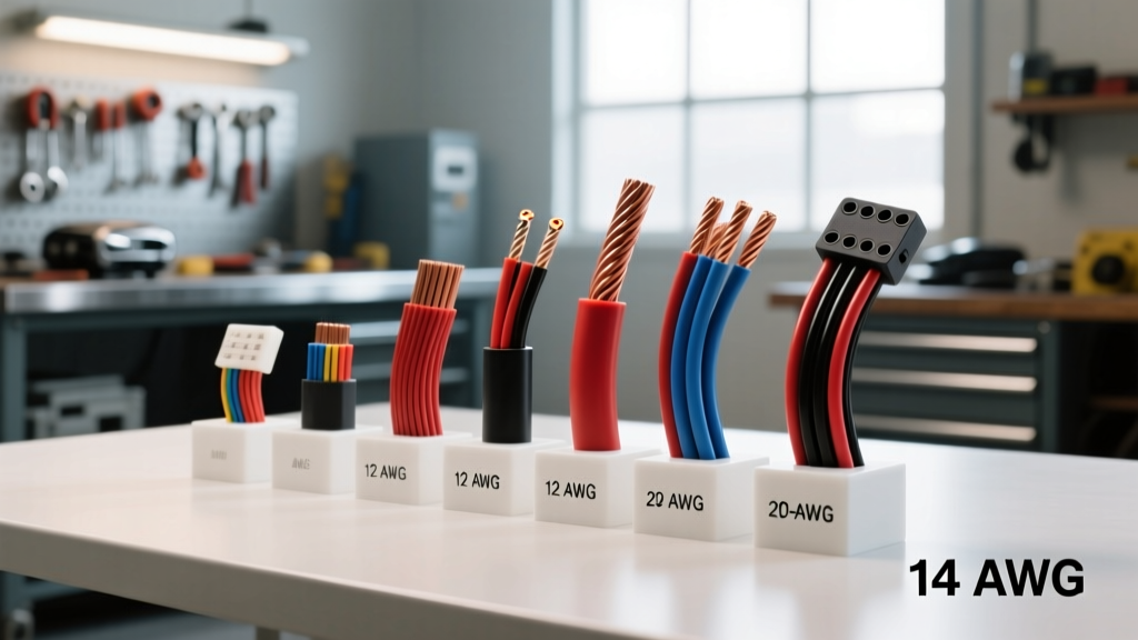
The Core Question: What Does Wire Gauge Mean?
If you are diving into automotive electrical repair or custom wiring, you have likely encountered the term AWG. But what does wire gauge mean exactly? In the American Wire Gauge (AWG) system, wire gauge is a standardized measurement of a wire's physical diameter and cross-sectional area. The most critical concept for beginners to grasp is the inverse relationship of the AWG scale: the lower the gauge number, the thicker the wire. For example, a heavy-duty 4-AWG battery cable is substantially thicker than a delicate 18-AWG wire used for a dashboard LED indicator.
Historically, the gauge number represented the number of times a raw copper rod was pulled through progressively smaller drawing dies to achieve the final diameter. A 12-AWG wire was pulled through fewer dies than an 18-AWG wire, leaving it thicker. Today, AWG strictly defines the cross-sectional area in circular mils, which directly dictates the wire's electrical resistance and its ability to carry current (ampacity) without overheating.
The Physics of Automotive Wire Sizing
Understanding what wire gauge means requires a basic understanding of electrical resistance. As electrons flow through a copper conductor, they encounter atomic friction, which generates heat. If a wire is too thin (gauge too high) for the amount of current (amperage) flowing through it, the heat buildup can melt the insulation, cause a short circuit, or even start an under-hood fire.
In a 12-volt automotive system, current draw is typically much higher than in a 120-volt household system to deliver the same wattage (Watts = Volts x Amps). A standard household 15-amp circuit uses 14-AWG wire. However, a 15-amp automotive fuel pump circuit requires a minimum of 12-AWG wire, and often 10-AWG, due to the longer continuous run lengths, higher ambient under-hood temperatures, and the strict requirement to minimize voltage drop. This is why applying household electrical logic to automotive wiring is a dangerous beginner mistake.
SAE J1128 vs. Standard AWG: Why Automotive Wire is Different
When researching what wire gauge means, beginners often confuse standard building wire (like THHN) with automotive primary wire. Automotive environments are brutal. Wires must withstand extreme heat, vibration, fuel exposure, and oil. The SAE J1128 Standard governs automotive primary wire specifications, ensuring the copper stranding and insulation can survive under-hood conditions.
There are three main types of SAE J1128 compliant wire you will encounter:
- GXL (General Cross-Linked): Features a cross-linked polyethylene (XLPE) insulation rated for 125°C. It is highly resistant to heat and abrasion, making it the gold standard for modern engine bay wiring.
- TXL (Thin-Wall Cross-Linked): Uses the same 125°C XLPE insulation but with a thinner wall. This saves weight and allows for tighter bending radii in complex harnesses, though it offers slightly less physical abrasion resistance than GXL.
- SGT (Standard General Thermoplastic): Uses PVC insulation rated only to 90°C. This is typically reserved for heavy-gauge battery cables (like 4-AWG or 2-AWG) routed in cooler areas, not for general engine bay harnesses.
Automotive Wire Gauge and Ampacity Reference Chart
The following chart outlines standard automotive AWG sizes, their maximum continuous ampacity ratings for chassis wiring (under-hood, bundled conditions), and their typical applications. Note that these ratings assume Oxygen-Free Copper (OFC) wire.
| AWG Size | Cross-Section (mm²) | Max Amps (Chassis) | Resistance per 1,000 ft (Ω) | Typical Automotive Application |
|---|---|---|---|---|
| 18 AWG | 0.82 mm² | 6A - 8A | 6.51 Ω | Headlight switch triggers, ECU sensor signals, LED lighting. |
| 16 AWG | 1.31 mm² | 10A - 12A | 4.09 Ω | Horn circuits, interior dome lights, windshield wiper motors. |
| 14 AWG | 2.08 mm² | 15A - 18A | 2.57 Ω | Fuel injectors, power window motors, cigarette lighter sockets. |
| 12 AWG | 3.31 mm² | 20A - 25A | 1.62 Ω | High-amperage fuel pumps, H4 headlight power feeds, radiator fans. |
| 10 AWG | 5.26 mm² | 30A - 40A | 1.02 Ω | Main relay feeds, high-wattage off-road light bars, starter solenoids. |
| 4 AWG | 21.15 mm² | 120A - 150A | 0.25 Ω | Main battery to starter motor cables, high-output alternator charging. |
Real-World Application: Building a 12-AWG Headlight Relay Harness
To truly understand what wire gauge means in practice, let us look at a common automotive upgrade: installing a relay harness for H4 halogen headlights. Factory headlight switches often route full headlight current through the dashboard switch and thin 16-AWG or 18-AWG wires. This causes severe voltage drop, resulting in dim lights and melted switches.
By building a custom harness, we bypass the factory wiring for the heavy current, using the factory wire only as a low-current trigger. Here is the exact specification for a robust, single-headlight relay circuit using a standard Bosch-style 5-pin relay (using 4 pins):
- Pin 30 (Power Input): Use 10-AWG Red wire. Run this directly from the positive battery terminal through a 20-amp inline ATC fuse holder. 10-AWG is used here to ensure zero voltage drop over the long run from the battery to the relay.
- Pin 87 (Normally Open Output): Use 12-AWG Red wire. Run this from the relay to the H4 headlight connector (Pin 3 for low beam). 12-AWG is perfectly sized for the 5-amp to 8-amp draw of a standard 55W H4 bulb over the short 3-foot run.
- Pin 86 (Coil Trigger): Use 18-AWG White wire. Splice this into the factory headlight positive wire. Since this only powers the relay's internal electromagnetic coil (drawing less than 0.2 amps), 18-AWG is more than sufficient.
- Pin 85 (Coil Ground): Use 18-AWG Black wire. Route this to a clean, bare-metal chassis ground point.
This configuration highlights how wire gauge is selected based on the specific current draw and length of each individual segment of a circuit, rather than using a single gauge for the entire harness.
Understanding Voltage Drop in 10-AWG and 12-AWG Circuits
Ampacity is only half the story when determining what wire gauge means for your project. Voltage drop is the silent killer of automotive electronics. As current travels through a wire, resistance causes the voltage to decrease by the time it reaches the load. Automotive computers, fuel pumps, and HID ballasts require a minimum of 12.0 to 12.5 volts to operate correctly. If voltage drops below 11.5 volts, a fuel pump will run slower, leaning out the engine, or an ECU may reset entirely.
The formula for calculating voltage drop in a DC circuit is:
Voltage Drop = (2 x Length x Current x Resistance per 1,000 ft) / 1,000
Example: You are wiring an aftermarket 15-amp electric fuel pump located 10 feet away from the battery (20 feet total round-trip circuit length) using 12-AWG wire. According to our chart, 12-AWG has a resistance of 1.62 Ω per 1,000 ft.
- VD = (2 x 10 x 15 x 1.62) / 1000
- VD = 486 / 1000
- VD = 0.486 Volts
A drop of 0.48V is acceptable (under the 3% rule for critical circuits). However, if you mistakenly used 16-AWG wire (4.09 Ω/1000ft), the drop would be 1.22 Volts. At the pump, you would only have 11.3V (assuming a 12.5V alternator output), which could cause fuel starvation under heavy load. For deeper technical calculations and wire sizing tools, resources like the Del City Wire Technical Resources library provide excellent calculators and reference charts.
CCA vs. OFC: The Hidden Gauge Trap
When buying wire, you will encounter two distinct materials: Oxygen-Free Copper (OFC) and Copper-Clad Aluminum (CCA). CCA wire features an aluminum core with a thin copper plating. Because aluminum is a poorer conductor than copper and has a higher resistance, a 12-AWG CCA wire will perform more like a 14-AWG OFC wire. CCA is also highly susceptible to galvanic corrosion when crimped with standard copper terminals, leading to high-resistance connections and melted connectors over time.
For any critical automotive circuit—especially high-amperage runs like audio amplifiers, winches, or electric cooling fans—always insist on 100% OFC wire. If you are forced to use CCA wire due to budget constraints, you must step up one full AWG size (e.g., use 10-AWG CCA where 12-AWG OFC is specified) to compensate for the increased resistance.
Common Beginner Wiring Mistakes
Now that you understand what wire gauge means, avoid these frequent pitfalls that lead to electrical failures:
- Using Solid Core Wire: Never use solid core household wire in a vehicle. The constant engine vibration will cause solid copper to work-harden, snap, and short out against the chassis. Always use multi-strand automotive primary wire.
- Undersizing the Ground Wire: The ground wire must be the exact same AWG size as the positive power wire. A 10-AWG power wire feeding a winch solenoid is useless if the ground path relies on a rusty 14-AWG factory chassis strap.
- Over-Fusing the Wire: The fuse protects the wire, not the component. If you use 12-AWG wire rated for 20 amps, your inline fuse must not exceed 20 amps. Putting a 30-amp fuse on a 12-AWG wire means the wire will melt and catch fire before the fuse blows during a dead short.
- Ignoring Connector Ratings: A 12-AWG wire might handle 25 amps, but the standard .250-inch spade terminal you crimped onto it might only be rated for 15 amps before overheating. Always match your terminal size and plating (use nickel-plated or heat-shrink sealed terminals) to the current draw.
By respecting the physical limitations of AWG sizing and adhering to SAE standards, you ensure that your vehicle's electrical system remains safe, reliable, and capable of handling the demanding loads of modern automotive accessories.