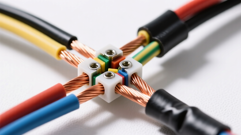
Introduction to High-Amperage 6 AWG Circuit Splicing
Splicing 6 gauge wire in automotive, off-road, and marine electrical systems represents a critical threshold in high-amperage circuit design. At this gauge, circuits typically carry 60 to 150 amps, powering essential high-load components such as upgraded alternators, electric winches, EV battery management systems, and high-output audio amplifiers. A poorly executed splice in a 6 AWG circuit does not merely cause a voltage drop; it creates a severe fire hazard due to thermal runaway. This advanced technical deep dive explores the metallurgical, mechanical, and electrical specifications required to properly splice 6 gauge wire in harsh, high-vibration automotive environments.
Electrical and Physical Specifications of 6 AWG Wire
Understanding the baseline physical properties of 6 AWG wire is mandatory before selecting splicing hardware. In automotive applications, 6 AWG wire is almost exclusively stranded to withstand chassis vibration and engine movement. According to the SAE J1128 Standard, automotive wire must meet strict stranding and flexibility requirements to prevent fatigue-induced strand fracture.
| Specification | SAE J1128 / AWG Standard Value |
|---|---|
| AWG Size | 6 AWG |
| Cross-Sectional Area | 13.30 mm² (26,240 Circular Mils) |
| Standard Stranding | 133 strands of 24 AWG or 259 strands of 30 AWG |
| Outer Diameter (OD) | ~0.184 inches (4.67 mm) bare copper |
| DC Resistance @ 20°C | 0.395 Ohms per 1,000 ft |
| Ampacity (Engine Bay, 105°C) | ~120 Amps (single wire in free air) |
| Ampacity (Passenger Cabin, 90°C) | ~150 Amps (per NFPA 70 (NEC) Article 310 baseline) |
Insulation Types: TXL vs. GXL vs. SGX
When splicing 6 AWG wire, you must match the terminal and heat shrink to the insulation type. TXL (Thin-wall, 125°C) is common in OEM harnesses but can be easily damaged during stripping. GXL (General-purpose, 125°C) offers slightly thicker insulation for aftermarket routing. SGX (Cross-linked Polyethylene, 150°C) features the thickest insulation and is mandatory for 6 AWG battery cables routed near exhaust manifolds or turbochargers. Stripping SGX requires a heavy-duty ratcheting stripper calibrated precisely to 6 AWG; using a standard blade knife will nick the outer copper strands, reducing the cross-sectional area and creating a localized resistance hotspot.
Failure Modes in 6 Gauge Splices
High-current splices fail due to three primary mechanisms: vibration fatigue, thermal degradation, and galvanic corrosion. Unlike low-amperage signal wires, a 6 AWG wire carrying 100 amps will generate significant heat at any point of increased resistance. If a splice relies solely on solder, the continuous thermal cycling of an engine bay can cause the solder to soften (solder melts at ~183°C to 190°C, but loses structural rigidity much lower). Combined with engine vibration, a solder-only 6 AWG splice will eventually suffer from fatigue cracking, leading to arcing and catastrophic failure. Furthermore, using acid-core flux or hardware-store crimp connectors with dissimilar metals (like tinned steel instead of electrolytic copper) introduces galvanic corrosion, which rapidly increases resistance over time.
Approved Methods for Splicing 6 Gauge Wire
Method 1: Heavy-Duty Adhesive-Lined Heat Shrink Crimping
The industry gold standard for splicing 6 AWG automotive wire is the closed-barrel hex crimp using adhesive-lined heat shrink terminals. This method requires a heavy-duty ratcheting crimper or a 12-ton hydraulic crimper (such as the Milwaukee M18 FORCE LOGIC). The hex crimp profile uniformly compresses the copper strands and the terminal barrel, causing the copper to cold-weld under extreme pressure (exceeding 10,000 PSI at the die interface). This eliminates air pockets, preventing oxygen ingress and subsequent oxidation.
| Crimp Parameter | Specification for 6 AWG |
|---|---|
| Terminal Material | Electrolytic Copper (ETP), Tin-Plated |
| Crimp Profile | Hexagonal (Nest/Indent for solid, Hex for stranded) |
| Pull-Out Force | > 250 lbs minimum |
| Heat Shrink Material | Dual-Wall Polyolefin with EVA Adhesive Inner Layer |
| Shrink Ratio | 3:1 or 4:1 |
The dual-wall heat shrink is critical. The outer layer is cross-linked polyolefin that shrinks at ~120°C to provide mechanical protection. The inner layer is an ethylene-vinyl acetate (EVA) copolymer that melts at ~80°C, flowing deeply into the interstices of the stranded wire and the terminal barrel to create a 100% waterproof, corrosion-proof seal. This is the exact methodology recommended in the West Marine DC Wiring Guide for harsh, high-vibration, high-moisture environments.
Method 2: High-Temperature Soldering with Copper Sleeves
While crimping is preferred for chassis and engine bay wiring, soldering is acceptable for 6 AWG splices in low-vibration, sealed environments (such as inside an audio amplifier enclosure or a sealed battery box). If soldering 6 AWG wire, you must use a high-wattage soldering iron (minimum 150W) or a MAP/Pro gas torch with a dedicated copper cradle. Never use acid-core flux; use only high-grade rosin-core flux designed for electrical work. To prevent solder wicking—which turns flexible stranded wire into a rigid, brittle solid that snaps under vibration—stagger the wire strands slightly and apply heat only to the copper sleeve, allowing capillary action to draw the solder in. Always seal the soldered joint with 3M MDT dual-wall adhesive heat shrink.
Real-World Automotive Applications
Alternator Upgrade: GM LS Engine Swap
When performing an LS engine swap utilizing a 200A alternator, the OEM 8 or 10 AWG charge wire is insufficient and will cause severe voltage drop and alternator overheating. Upgrading to 6 AWG Red (B+) wire is required. Splicing 6 AWG wire in this application typically involves integrating an inline 250A ANL fuse holder near the starter junction block. The splice must utilize 3/8" (10mm) closed-barrel ring terminals. When bolting the 6 AWG ring terminal to the busbar or ANL fuse block, torque the hardware to 12-15 ft-lbs using a belleville (conical) washer. The belleville washer maintains clamping force as the copper expands and contracts under heavy thermal cycling, preventing the terminal from loosening over time.
Winch Solenoid and Control Circuits
On off-road vehicles like the Jeep Wrangler JK or Ford F-250, a 12,000 lb winch can draw upwards of 450A under stall load. While the main winch cables are often 1/0 or 2/0 AWG, the heavy-duty contactor solenoids and auxiliary charging circuits frequently utilize 6 AWG Black (Ground) and Yellow (Switched Power) wires. Splicing these 6 AWG control wires requires step-down heat shrink butt splices if transitioning from 6 AWG to 8 AWG at the relay block. Ensuring a watertight seal here is paramount, as off-road vehicles are frequently subjected to deep water crossings and high-pressure mud/salt spray.
Testing and Validation Protocols
Visual inspection is insufficient for validating a 6 AWG splice. Professional automotive electricians rely on two definitive tests:
- The Millivolt Drop Test: With the circuit under a realistic load (e.g., 50A-80A), use a high-precision digital multimeter to measure the voltage drop directly across the splice joint (from the bare wire on one side to the bare wire on the other). A properly executed 6 AWG hex crimp should exhibit a voltage drop of less than 10 millivolts (0.010V). Any reading above 50mV indicates excessive internal resistance and requires the splice to be cut and redone.
- Thermal Imaging (FLIR): After running the high-amperage load for 3 to 5 minutes, scan the splice with a thermal imaging camera. The splice joint should be within 2°C to 3°C of the ambient wire temperature. A hotspot at the crimp barrel indicates poor strand compression, internal voids, or oxidation.
Conclusion
Splicing 6 gauge wire demands strict adherence to automotive electrical standards, precision tooling, and high-quality materials. By utilizing SAE J1128 compliant SGX or GXL wire, executing cold-weld hex crimps with dual-wall adhesive heat shrink, and validating the joint via millivolt drop testing, technicians can ensure that high-amperage circuits remain safe, efficient, and resilient against the extreme conditions of the automotive environment.