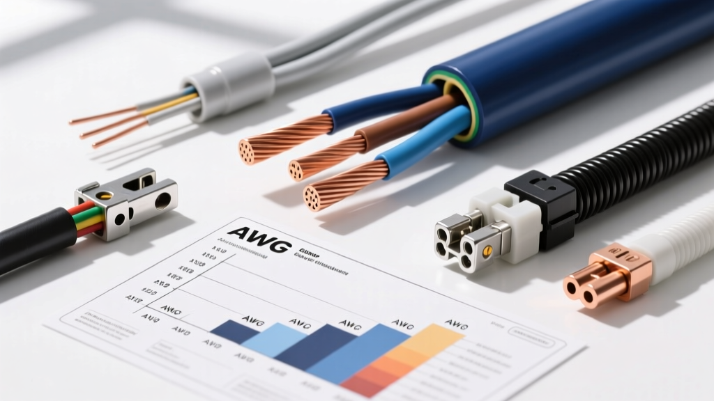
Why We Must Explain Wire Gauge for High-Amp Alternator Upgrades
Upgrading to a 250-amp alternator on a modified 2007-2018 Jeep Wrangler JK, a 1999-2006 Chevy Silverado, or a dedicated off-road rig is a common necessity when adding high-draw accessories like 12,000-lb winches, high-wattage LED light bars, or massive car audio amplifiers. However, the factory 4 AWG or 6 AWG charging wire will quickly become a severe bottleneck. Pushing 200+ amps through undersized factory wiring leads to catastrophic voltage drop, melted insulation, and potential electrical fires. When planning this modification, master technicians must clearly explain wire gauge requirements to ensure the new high-output charging system operates safely, efficiently, and reliably under heavy continuous loads.
The Inverse Logic of AWG and Automotive Standards
The American Wire Gauge (AWG) system is notoriously counterintuitive to beginners: as the gauge number decreases, the wire diameter and current-carrying capacity (ampacity) increase. A 1/0 AWG (read as 'one-aught') wire is significantly thicker and more capable than a 4 AWG wire. Furthermore, automotive electrical systems require adherence to specific insulation and stranding standards.
Standard automotive primary wire (SAE J1128) features fewer, thicker copper strands and a rigid PVC jacket. While fine for low-draw factory sensor circuits, it is entirely unsuitable for high-amperage alternator upgrades. The rigid strands fatigue and snap under constant engine vibration. Instead, professionals specify fine-strand welding cable (often meeting SAE J1127 or ABYC marine standards). Fine-strand copper offers superior flexibility, resisting vibration-induced work-hardening while providing a denser copper cross-section for better conductivity.
12V DC Wire Ampacity Specification Chart
To properly size your main B+ charging cable, you must calculate the maximum expected continuous load, not just the alternator's peak rating. A 250A alternator rarely outputs its maximum rating continuously; however, the wire must be sized to handle the peak output with a 20% safety buffer to prevent insulation melting in high-heat engine bays. The following chart is based on MAD Enterprises and ABYC standards for 12V DC engine bay runs up to 15 feet, maintaining a strict 3% maximum voltage drop.
| Wire Gauge (AWG) | Max Continuous Amps | Resistance (Ohms/1000ft) | Recommended Application |
|---|---|---|---|
| 4 AWG | 120A | 0.2485 | Stock 105A-130A Alternators |
| 2 AWG | 160A | 0.1563 | Upgraded 160A-180A Alternators |
| 1 AWG | 190A | 0.1239 | 200A Alternators, Short Runs |
| 1/0 AWG | 225A | 0.0983 | 225A-250A Alternators (Standard) |
| 2/0 AWG | 260A | 0.0779 | 250A+ Alternators, Long Runs/Dual Battery |
Executing the 250A Upgrade: Step-by-Step Wiring Protocol
Step 1: Selecting and Routing the Main B+ Cable
For a typical 250A Denso-style or GM AD244 alternator upgrade, 2/0 AWG fine-strand tinned copper is the gold standard. Use a red jacket for the main positive B+ cable and a black jacket for the auxiliary chassis ground. Route the cable away from exhaust manifolds and steering shafts. Protect the entire length with split-loom tubing, and wrap the loom in high-temperature Tesa cloth tape to prevent chafing and rattling against the firewall or inner fender.
Step 2: Terminal Selection and Hydraulic Crimping
Never use cheap, stamped sheet-metal ring terminals for high-amp circuits. Use heavy-duty, oxygen-free copper (OFC) ring terminals with a 3:1 adhesive-lined marine-grade heat shrink neck. For the alternator B+ post, a 5/16-inch ring terminal is typically required, while the battery side usually requires a 3/8-inch terminal.
Critical Crimping Note: Do not solder the main B+ connections. Solder wicks into the fine copper strands via capillary action, creating a rigid 'stress riser' right where the wire enters the terminal. Under engine vibration, this rigid section will snap. Instead, use a hex-die hydraulic crimper to apply a uniform, cold-weld hex crimp. Heat the adhesive-lined shrink until the marine sealant squeezes out of both ends, ensuring a completely watertight seal against battery acid and road salt.
Step 3: Torque Specifications
Proper torque is vital. The M8 nut on a typical alternator B+ stud requires exactly 10-12 Nm (7.4-8.9 lb-ft). Over-torquing this nut will strip the threads or, worse, crack the internal diode bridge mounting plate, instantly destroying the new alternator. The battery terminal clamp should be torqued to 9-11 Nm.
Sense Wires and Connector Pinouts
High-output alternators require a dedicated 'sense' wire to monitor actual battery voltage. If you are upgrading a GM vehicle using the AD244 or CS130D 4-pin connector, the pinout is critical:
- Pin A (L - Lamp): Connects to the dashboard battery light circuit (usually 18 AWG).
- Pin B (S - Sense): MUST connect directly to the battery positive post or main distribution block. Use 14 AWG wire. If connected to the alternator B+ post, the alternator will compensate for voltage drop in the main cable by overcharging the battery.
- Pin C (I - Ignition): Switched 12V source to wake the regulator (18 AWG).
- Pin D (F - Field): PWM signal to the PCM for idle-up compensation (leave disconnected on standalone aftermarket setups).
For 1-wire Denso upgrades (common in Jeep and Toyota mods), the sense is internal. However, this makes the main B+ cable gauge even more critical, as the internal sense reads voltage directly at the alternator stud, meaning any voltage drop in the main cable will result in the battery receiving less than 14.4V.
Real-World Failure Modes and Voltage Drop Testing
If you fail to properly explain wire gauge selection and install an undersized cable (e.g., using 2 AWG for a 250A load), you will encounter specific failure modes:
- Melted Insulation: The wire will physically heat up under heavy load (like winching), melting the PVC jacket and shorting against the chassis.
- Alternator Diode Failure: If the main cable has high resistance, the battery will sit at 12.8V while the alternator B+ post reads 14.8V. The internal regulator will push maximum field current continuously to try and raise battery voltage, eventually cooking the rectifier diodes.
- Audio Whining / Ripple Current: Undersized ground wires (always match the positive gauge with an equal negative ground to the chassis/battery) fail to filter alternator ripple current, resulting in a high-pitched whine in car audio systems that changes pitch with engine RPM.
The Diagnostic Fix: Perform a voltage drop test. With the engine running at 2,000 RPM and heavy accessories turned on, place your multimeter's red probe on the alternator B+ post and the black probe on the battery positive terminal. A healthy, properly gauged 2/0 AWG cable will show a voltage drop of less than 0.2V. If your meter reads 0.5V or higher, your wire gauge is too small, your crimps are failing, or your terminals are corroded.