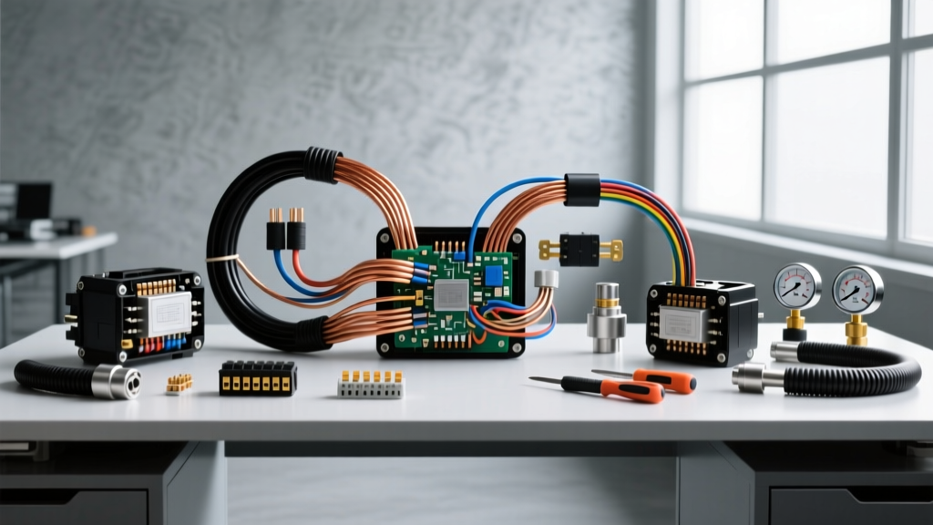
Introduction to Wire Gauge Machines in Automotive Harness Manufacturing
In modern automotive electrical systems, the precision of the wiring harness is paramount. A wire gauge machine in this context refers to two critical pieces of manufacturing and quality control equipment: automated wire processing machines (which cut, strip, and crimp based on specific AWG inputs) and inline laser micrometer gauge machines (which verify the physical dimensions and cross-sectional area of the copper conductors). Whether you are building a custom harness for a 2020+ GM LS-swapped chassis or mass-producing OEM engine bay looms, understanding the technical specifications, calibration tolerances, and crimping parameters of these machines is essential for preventing voltage drop, terminal back-out, and insulation failures.
This technical reference outlines the exact AWG-to-metric conversions, stripping tolerances, and crimping force specifications required to calibrate wire gauge machines for standard automotive connectors, including the TE AMP Superseal 1.5 series and the Deutsch DT environmentally sealed connectors.
Core Specifications: AWG vs. Metric Cross-Sectional Area
North American automotive design heavily utilizes the American Wire Gauge (AWG) system, while global platforms and European manufacturers (like BMW and Volkswagen) rely on metric cross-sectional areas (mm²). Advanced wire gauge processing machines must be calibrated to account for the stranded variations permitted by SAE J1128 Low Tension Cable standards. For instance, while 18 AWG is nominally 0.82 mm², the actual copper area can vary between 0.75 mm² and 0.85 mm² depending on the stranding class (e.g., 19-strand vs. 41-strand). The machine's stripping blades must be set to the insulation outer diameter (OD), not just the conductor gauge, to prevent nicking the copper strands.
Table 1: Machine Calibration Tolerances by AWG (TXL Insulation)
| AWG Size | Nominal Area (mm²) | Conductor Dia. (mm) | TXL Insulation OD (mm) | V-Blade Clearance (mm) | Strip Length Tolerance |
|---|---|---|---|---|---|
| 20 AWG | 0.52 | 0.81 | 1.40 - 1.60 | 0.85 ± 0.02 | ± 0.15 mm |
| 18 AWG | 0.82 | 1.02 | 1.65 - 1.85 | 1.05 ± 0.02 | ± 0.15 mm |
| 16 AWG | 1.31 | 1.29 | 1.95 - 2.20 | 1.35 ± 0.03 | ± 0.20 mm |
| 14 AWG | 2.08 | 1.63 | 2.35 - 2.60 | 1.70 ± 0.03 | ± 0.20 mm |
| 12 AWG | 3.31 | 2.05 | 2.80 - 3.10 | 2.15 ± 0.04 | ± 0.25 mm |
Stripping and Crimping Parameters for Common Automotive Connectors
When programming a wire gauge machine for terminal crimping, the crimp height and crimp width are far more critical than the raw wire gauge. An improperly calibrated crimp press will result in either a cold weld (leading to high resistance and thermal failure) or crushed strands (reducing the ampacity rating). Below are the exact specifications for processing 14 AWG and 16 AWG wires into two of the most common automotive connectors.
Deutsch DT Series & TE Superseal Processing Specs
The Deutsch DT series utilizes solid barrel crimps that require precise wire preparation. For a 2-way DT connector (e.g., controlling a PWM cooling fan), Pin 1 might carry a 14 AWG Red (RD) power wire, while Pin 2 carries a 14 AWG Black (BK) ground wire. The wire gauge machine must strip exactly 6.0 mm of insulation to ensure the brush (the visible copper strands extending past the terminal barrel) is exactly 0.5 mm to 1.0 mm, as mandated by IPC/WHMA-A-620 standards.
Table 2: Crimping Force and Dimensional Specifications
| Connector System | Terminal Type | Wire Gauge | Crimp Height (mm) | Crimp Width (mm) | Min. Pull-Out Force (N) |
|---|---|---|---|---|---|
| TE AMP Superseal 1.5 | Female Receptacle | 16 AWG (1.31 mm²) | 1.15 - 1.25 | 1.80 - 1.90 | 110 N |
| TE AMP Superseal 1.5 | Male Tab | 14 AWG (2.08 mm²) | 1.45 - 1.55 | 2.20 - 2.30 | 150 N |
| Deutsch DT | Solid Barrel Pin | 16 AWG (1.31 mm²) | 1.20 - 1.30 | 1.75 - 1.85 | 120 N |
| Deutsch DT | Solid Barrel Socket | 14 AWG (2.08 mm²) | 1.50 - 1.60 | 2.30 - 2.40 | 160 N |
Laser Micrometer Gauge Machines for Wire Diameter Verification
Beyond cutting and stripping, the term wire gauge machine also applies to inline laser micrometers used during the extrusion of automotive primary wire (like GXL and TXL) and during incoming quality control (IQC) at harness assembly plants. These machines project a laser beam across the wire at high speeds (up to 3,000 Hz) to measure the outer diameter and detect any eccentricity in the insulation or deviations in the copper stranding.
For automotive applications, the laser gauge machine must be calibrated to a tolerance of ±0.002 mm. If a spool of 12 AWG SAE J1128 GXL wire is measured, the machine expects an OD between 2.80 mm and 3.10 mm. If the laser detects a continuous reading of 3.15 mm, the machine triggers an alarm, as the oversized insulation will cause the wire to jam in the automated stripping blades or fail to seat properly in the rear seal grommets of weatherproof connectors.
Color Code Verification and Sensor Integration
Modern wire gauge processing machines are equipped with inline optical sensors to verify wire color codes before the cutting blade engages. This prevents catastrophic harness mis-wiring. According to standard automotive color codes (often derived from SAE or manufacturer-specific standards like Ford WPT-978), the machine's optical sensor must distinguish between base colors and tracer stripes.
- BK (Black): Typically used for chassis grounds or high-current return paths (8 AWG to 4 AWG).
- RD (Red): Battery positive, fused power feeds (14 AWG to 10 AWG).
- GN (Green): Often used for sensor signals or CAN bus lines (18 AWG to 20 AWG).
- YE (Yellow): Airbag system circuits (SRS), requiring specialized shorting-bar terminals.
If the machine's optical sensor detects a YE (Yellow) wire but the programmed harness manifest calls for a GN (Green) signal wire for an ABS wheel speed sensor, the machine instantly halts the feed mechanism to prevent a safety-critical wiring fault.
Troubleshooting Machine Calibration Errors & Harness Failures
Even highly calibrated wire gauge machines experience drift, mechanical wear, and sensor fouling. Below is a technical decision tree for troubleshooting common processing faults on the manufacturing floor or in high-volume custom harness shops.
Symptom: Conductor Strand Nicking or Severing During Stripping
- Cause: The V-blade depth on the stripping mechanism is set too aggressively, cutting into the copper strands rather than just scoring the TXL insulation. This often happens when switching from 14 AWG to 16 AWG without updating the machine's AWG profile.
- Fix: Recalibrate the blade clearance using a feeler gauge. For 16 AWG, set the blade gap to exactly 1.35 mm. Verify the cut by examining the stripped end under a 10x loupe; zero copper strands should be flattened or severed.
Symptom: Insulation Pull-Back (Insulation Creep) Post-Crimping
- Cause: The strip length tolerance was exceeded, or the wire was stretched by the feed rollers prior to crimping. When the wire relaxes, the insulation pulls back, exposing bare copper to moisture and risking corrosion inside the connector cavity.
- Fix: Reduce the feed roller pneumatic pressure. Ensure the strip length is programmed to the exact terminal barrel depth plus 1.0 mm for the brush. Reference TE Connectivity Application Specifications for exact bellmouth requirements.
Symptom: Asymmetric Crimp Profile (Crimp Height Out of Spec)
- Cause: The terminal applicator is misaligned, or the crimping press ram has excessive lateral play. This results in one side of the terminal barrel being crushed while the other is loose, failing the pull-out force test.
- Fix: Perform a crimp cross-section analysis (micrograph). Adjust the applicator shut height and verify the terminal feed track is perfectly centered with the ram. Re-test pull-out force to ensure it meets the minimum 110 N requirement for 16 AWG circuits.
Conclusion
Mastering the specifications of a wire gauge machine requires a deep understanding of both the physical properties of automotive wire and the mechanical tolerances of the processing equipment. By strictly adhering to SAE J1128 dimensional standards, maintaining precise V-blade clearances, and validating crimp heights against IPC/WHMA-A-620 criteria, technicians and engineers can ensure that every wire in the harness delivers optimal conductivity, mechanical retention, and environmental sealing.