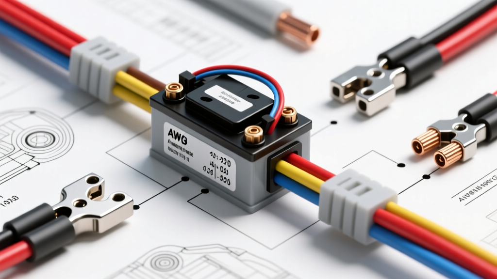
Why Battery Cable Wire Gauge Matters in High-Amp Systems
Upgrading an automotive electrical system for high-draw accessories—such as winches, high-output alternators, or massive car audio amplifiers—requires a fundamental understanding of current flow. Selecting the correct battery cable wire gauge is the single most critical factor in preventing voltage drop, overheating, and catastrophic electrical fires. Unlike 120V AC household wiring, a 12V DC automotive system operates at a fraction of the voltage, meaning it must push exponentially higher amperage to deliver the same wattage. According to Ohm's Law, as amperage increases, the resistance of the conductor generates heat. If your battery cable wire gauge is too thin for the load, the cable becomes a heating element rather than a conductor.
Starter motors alone can draw between 150A and 250A during initial cranking, while heavy-duty winches can spike well over 400A under maximum load. Factory wiring is engineered strictly for stock electrical loads with minimal safety margins. When modifying a vehicle, calculating and installing the proper battery cable wire gauge ensures that your high-amp accessories receive the voltage they need to operate efficiently without starving the ECU or damaging sensitive electronics.
The Danger of CCA vs. OFC Copper
Before cutting your new battery cable wire gauge, you must verify the conductor material. The market is flooded with Copper-Clad Aluminum (CCA) wire, which is significantly cheaper than pure copper. However, aluminum has roughly 61% of the conductivity of copper by volume. A 2 AWG CCA cable will perform electrically like a 4 AWG pure copper cable, leading to severe voltage drop and potential melting under high-amperage cranking loads.
For any automotive battery cable wire gauge installation, you must use Oxygen-Free Copper (OFC) or high-strand-count pure copper wire that meets the SAE J1128 Low Tension Primary Cable Standard. Type SGT battery cable is the industry benchmark, featuring a high strand count (e.g., 2115 strands of 30 AWG wire for a 2 AWG cable) which provides the extreme flexibility needed to route through tight engine bays while maintaining maximum conductivity.
Calculating Your Required Battery Cable Wire Gauge
To determine the exact battery cable wire gauge for your application, you must calculate the total maximum continuous amperage draw and the total length of the cable run (positive and negative combined). The engine bay environment also requires severe derating due to ambient temperatures regularly exceeding 125°C (257°F) near the exhaust manifolds. Refer to the Madsen Wire Battery Cable Specifications and the ampacity chart below to select your gauge.
| AWG Size | Strand Count (SAE J1128) | Max Amps (Engine Bay 125°C) | Max Amps (Chassis 90°C) | Resistance (Ohms/1000ft) |
|---|---|---|---|---|
| 4 AWG | 1332 | 120A | 160A | 0.2485 |
| 2 AWG | 2115 | 160A | 210A | 0.1563 |
| 1/0 AWG | 2667 | 210A | 270A | 0.0983 |
| 2/0 AWG | 3379 | 260A | 330A | 0.0779 |
| 4/0 AWG | 5423 | 360A | 450A | 0.0490 |
Step-by-Step Installation Guide for Upgraded Battery Cables
Proper installation goes far beyond simply bolting a thicker wire to the battery terminal. Follow these steps to ensure a permanent, low-resistance connection.
Step 1: Measuring, Cutting, and Stripping
Always route a flexible measuring tape along the exact path the cable will take, avoiding sharp edges and hot exhaust components. Add 6 to 8 inches to your measurement to allow for service loops and drip loops. When stripping the heavy-gauge insulation, use a specialized rotary cable stripper or a sharp utility knife. Score the jacket longitudinally and peel it back; never cut circumferentially, as nicking even a few of the fine copper strands will create a weak point that will eventually snap under engine vibration.
Step 2: Terminal Selection and Hex Crimping
Use only tinned copper ring terminals rated for your specific battery cable wire gauge. Tinning prevents galvanic corrosion and oxidation under the crimp barrel. For high-amp applications, a hex-crimp die is vastly superior to an indenter-style crimper. A hex crimp compresses the barrel uniformly, cold-welding the copper strands and the terminal together into a solid mass, maximizing surface area contact and minimizing electrical resistance. If you lack a heavy-duty hydraulic hex crimper, consult local Painless Performance Wiring Manuals for alternative mechanical leverage tools designed for 2/0 and 4/0 AWG lugs.
Step 3: Sealing with Dual-Wall Polyolefin
Never use standard PVC heat shrink on battery terminals. You must use dual-wall polyolefin heat shrink tubing with an internal hot-melt adhesive lining. Slide the tubing over the cable before crimping. After crimping, center the tubing over the barrel and the exposed wire strands. Apply heat evenly with a heat gun (not an open flame) until the tubing shrinks tightly and the adhesive purges slightly from the ends. This creates a 100% waterproof, airtight seal that prevents battery acid fumes from creeping under the insulation and turning the copper green.
Step 4: Routing and Loom Protection
Route the positive battery cable wire gauge away from the exhaust manifolds. If the cable must pass within 6 inches of a heat source, you must sleeve it in silicone-coated fiberglass fire sleeve (often rated to 500°F). Secure the cables every 12 to 18 inches using UV-resistant nylon cable ties or stainless steel P-clamps with rubber cushions to prevent chafing against the chassis or engine block.
Step 5: Termination and Torque Specifications
Clean the battery posts and cable lugs with a stainless steel wire brush until the metal is bright and shiny. Apply a thin layer of conductive anti-oxidant grease (such as NO-OX-ID A-Special) to the mating surfaces to prevent future corrosion. Torque the hardware to the manufacturer's exact specifications:
- GM Side-Post Batteries (M8x1.25 thread): Torque to 12-15 ft-lbs. Over-torquing will crack the plastic battery case and cause acid leaks.
- SAE Top-Post Batteries (3/8"-16 thread): Torque the clamp bolts to 9-12 ft-lbs. Ensure the clamp is fully seated and not "bottoming out" on the battery post.
Voltage Drop Testing Procedure (Under Load)
The only way to verify that your chosen battery cable wire gauge is adequate is to perform a dynamic voltage drop test under maximum load. A static multimeter test will not reveal high-resistance faults.
- Set your digital multimeter to the DC millivolt (mV) scale.
- Place the red probe directly on the battery's positive post (not the clamp) and the black probe on the starter motor's main positive terminal.
- Disable the fuel pump or ignition system so the engine will crank but not start.
- Crank the engine for 5 seconds while observing the multimeter.
- A healthy positive cable should show a voltage drop of no more than 0.2V (200mV). For the negative ground circuit, place the probes on the battery negative post and the engine block; the drop should not exceed 0.1V (100mV).
Common Failure Modes and Troubleshooting
If your vehicle exhibits slow cranking, dimming headlights during audio transients, or melted cable insulation, your battery cable wire gauge is likely undersized, or a connection has failed. The most common failure mode in high-amp installs is the "false crimp." This occurs when the wire insulation is accidentally crimped inside the copper barrel, or when the strands were not fully inserted before crimping. Under heavy load, the high resistance at the false crimp generates intense localized heat, eventually melting the heat shrink and causing an open circuit. Always perform a physical "pull test" on your crimped lugs before installation; a properly hex-crimped 2 AWG terminal should withstand over 200 lbs of pull force without slipping.