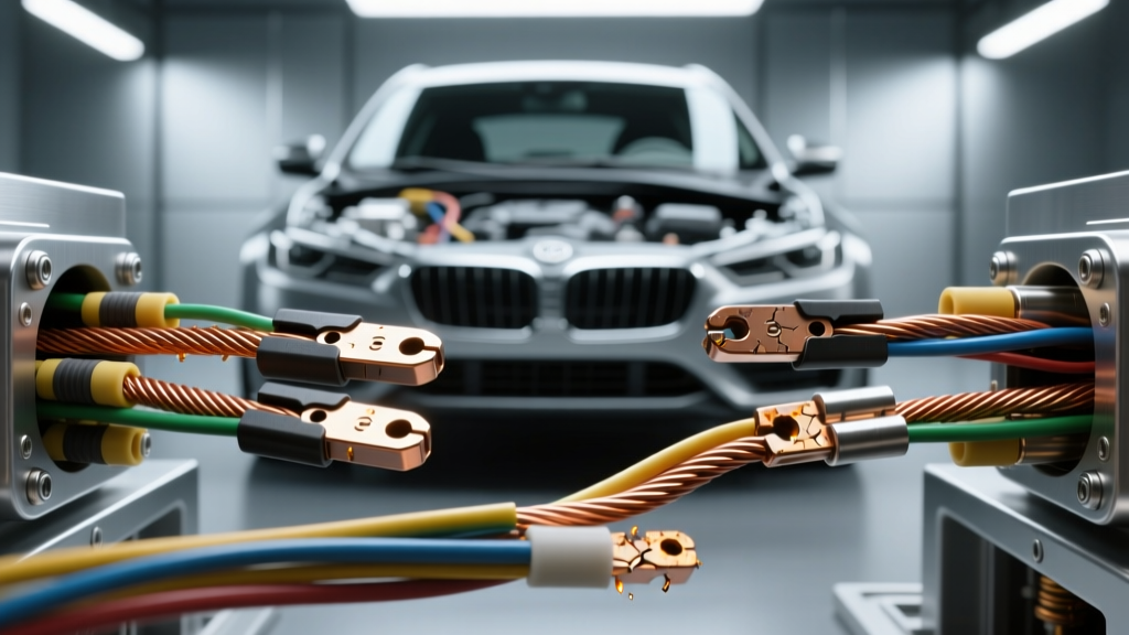
Understanding Zero Gauge Wire in High-Amperage Circuits
In high-performance automotive applications, EV conversions, and heavy-duty off-road builds, the electrical system demands massive current delivery. Upgrading to zero gauge wire (often colloquially interchanged with 1/0 AWG) is the standard solution for alternator upgrades, winch circuits, and high-output starter systems. However, simply installing thick copper does not guarantee a flawless circuit. Improper termination, routing errors, and misunderstood ampacity ratings frequently lead to voltage drop, thermal overload, and electromagnetic interference (EMI).
As an automotive electrical specialist, diagnosing issues in heavy-gauge circuits requires a systematic approach. Unlike 16 AWG lighting circuits where a bad ground simply kills the bulb, a failing 0 AWG connection can melt insulation, destroy alternator diodes, or cause a chassis fire. This guide provides a step-by-step troubleshooting flow for the most common zero gauge wire failure modes, backed by SAE J1128 battery cable standards and field-tested diagnostic procedures.
Technical Specifications: True 0 AWG vs. 1/0 AWG
A common point of confusion in the automotive aftermarket is the distinction between true 0 AWG and 1/0 AWG (One-Aught). While both are used for heavy current, 1/0 AWG is approximately 26% larger in cross-sectional area and is the true standard for high-amperage battery cables. Always verify the印字 (printing) on the wire jacket before diagnosing ampacity-related overheating.
| Specification | 0 AWG (True Zero) | 1/0 AWG (One-Aught) | 2 AWG (Reference) |
|---|---|---|---|
| Diameter (Inches) | 0.3249 | 0.3648 | 0.2576 |
| Cross-Section (kcmil) | 105.6 | 133.1 | 66.4 |
| Stranding (30 AWG equiv.) | 4,204 | 5,320 | 2,646 |
| Max Ampacity (Chassis, 105°C) | ~150A Continuous | ~170A Continuous | ~120A Continuous |
| Resistance (Ohms/1000ft @ 20°C) | 0.0983 | 0.0779 | 0.156 |
Note: Ampacity ratings assume single conductors in free air at 30°C ambient. Bundling wires or routing near exhaust components requires severe thermal derating.
Troubleshooting Flow 1: Diagnosing Voltage Drop
Symptom: Slow Cranking, Dimming Headlights, or Alternator Undercharging
Voltage drop is the silent killer of high-amperage circuits. When current flows through a resistance (such as a poorly crimped terminal or a corroded lug), voltage is lost as heat. According to standard diagnostic thresholds, a starter circuit should exhibit no more than 0.2V of total drop, while an alternator charging circuit should not exceed 0.5V drop under full load.
Step-by-Step Diagnostic Procedure
- Prep the Multimeter: Set your digital multimeter (DMM) to DC Volts. Ensure your probes are sharp enough to pierce minor surface oxidation on terminals.
- Test the Positive Side (Alternator to Battery): Place the red probe directly on the alternator B+ output stud (not the wire ring terminal, the actual metal stud). Place the black probe on the battery positive post. Start the engine, turn on the headlights and blower motor to max, and rev to 2,000 RPM. A reading above 0.5V indicates excessive resistance in the positive zero gauge wire.
- Test the Negative Side (Block to Battery): Place the red probe on the engine block (bare metal) and the black probe on the battery negative post. Crank the engine. A reading above 0.2V indicates a failing engine ground strap or poor battery-to-chassis connection.
- Isolate the Fault: If the positive side shows a 0.8V drop, move the red probe to the wire side of the crimp terminal. If the drop disappears, the fault is the crimp joint. If the drop remains, the fault is the wire length, internal strand corrosion, or the terminal eyelet interface.
Root Cause & Fix
The most common cause of voltage drop in zero gauge wire is 'hammer crimping' or using inadequate mechanical pliers. This leaves voids inside the barrel, reducing the effective conductive area. The Fix: Cut the terminal off. Strip the jacket using a precision wire stripper to avoid nicking the copper strands. Use a 6-ton hydraulic crimper with the correct hexagonal die for 1/0 AWG. Finish with 3:1 adhesive-lined marine heat shrink to prevent moisture intrusion and galvanic corrosion.
Troubleshooting Flow 2: Thermal Overload and Jacket Melting
Symptom: Wire Hot to the Touch, PVC Softening, or Burnt Smell
If your zero gauge wire is physically hot or the jacket is softening, the circuit is exceeding the thermal limits of the copper or the insulation material. Standard PVC-jacketed 0 AWG wire is typically rated for 105°C. However, ambient heat from the engine bay drastically reduces its current-carrying capacity.
Step-by-Step Diagnostic Procedure
- Measure True Amperage: Use a DC clamp meter around the zero gauge wire. Do not rely on the alternator's rated output; measure the actual continuous draw. If you are running a 250A alternator at continuous high output for off-road lighting or winching recovery, a true 0 AWG wire (rated ~150A continuous) is undersized.
- Inspect Routing and Ambient Temp: Check the wire's path. Is it zip-tied to the exhaust manifold, turbocharger downpipe, or cylinder head? For every 10°C rise in ambient temperature above 30°C, the wire's ampacity must be derated by approximately 10% to 15%.
- Check for Skin Effect and Harmonics: In high-end car audio applications utilizing massive Class D amplifiers, high-frequency AC ripple can cause the 'skin effect,' where current travels only on the outer strands of the wire, effectively reducing the gauge and causing localized heating.
Root Cause & Fix
Undersizing the wire for continuous duty or routing it through high-heat zones. The Fix: If continuous load exceeds 160A, upgrade to 2/0 AWG or 4/0 AWG welding cable. Reroute the wire away from exhaust components. If the wire must pass near a heat source, sleeve it in fiberglass fire-shield sleeving. Always specify XLPE (Cross-Linked Polyethylene) or EPDM insulation over standard PVC, as XLPE can withstand continuous temperatures up to 125°C-150°C without melting.
Troubleshooting Flow 3: EMI Interference and Alternator Whine
Symptom: High-Pitched Whine in Audio System or ECU Sensor Errors
Zero gauge wire carrying high, fluctuating DC current generates a significant electromagnetic field. If routed improperly, this field will induce alternating current (AC) noise into adjacent low-voltage signal wires, such as RCA audio cables, O2 sensor signal wires, or CAN bus lines.
Step-by-Step Diagnostic Procedure
- Verify the Noise Source: With the engine running, use an oscilloscope or a DMM set to AC Millivolts. Probe the RCA ground shield or the sensor signal return wire. If you see AC ripple that scales with engine RPM, you have EMI induction.
- Inspect Wire Routing: Trace the zero gauge power wire. Is it running parallel to the signal wires? Are they bundled together in the same split-loom through the firewall?
Root Cause & Fix
Parallel routing of high-current DC and low-voltage signal lines. The Fix: Reroute the zero gauge power wire and signal wires on opposite sides of the vehicle chassis. If they must cross, ensure they intersect at a strict 90-degree angle to minimize inductive coupling. Maintain a minimum separation of 18 inches wherever possible. For critical ECU sensor wires, utilize shielded twisted-pair (STP) cabling and ground the shield at the ECU end only.
Proper Termination: Torque Specifications and Hardware
Even a perfectly crimped zero gauge terminal will fail if the mechanical connection to the stud is flawed. Thermal cycling (heating under load, cooling at rest) causes metals to expand and contract. Over time, standard flat washers and split-ring lock washers will loosen, increasing resistance and creating a thermal runaway loop.
Hardware Selection
Never use star washers (toothed lock washers) on copper or aluminum terminal lugs. The teeth bite into the plating, exposing raw copper to oxygen and promoting galvanic corrosion, especially in the presence of road salt. Instead, use Belleville washers (conical spring washers). These washers act like a spring, maintaining constant clamping force on the terminal lug even as the metals expand and contract during thermal cycling.
Torque Specifications
Use a calibrated inch-pound or Newton-meter torque wrench to secure heavy-gauge lugs. Overtightening can snap the alternator B+ stud or strip the threads on a starter solenoid. Undertightening guarantees arcing and heat.
- M6 Stud (1/4 inch): 8 - 10 Nm (70 - 88 in-lbs)
- M8 Stud (5/16 inch): 15 - 18 Nm (130 - 160 in-lbs)
- M10 Stud (3/8 inch): 25 - 30 Nm (220 - 265 in-lbs)
By adhering to these torque specifications and utilizing proper Belleville hardware, you ensure a gas-tight mechanical connection that complements the electrical integrity of your zero gauge wire installation. For further reading on automotive grounding hierarchies and chassis bonding, refer to the technical bulletins provided by Painless Performance Products and the voltage drop calculation methodologies outlined by EC&M (Electrical Construction & Maintenance).