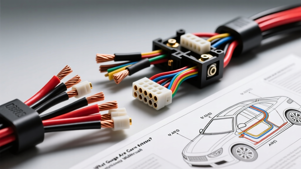
Introduction: Decoding the Car Stereo Wiring Harness
When installing an aftermarket head unit or integrating a complex car audio system, one of the most common questions we receive at Autoflow Wire is: what gauge are car stereo wires? Understanding the precise American Wire Gauge (AWG) specifications for your head unit's wiring harness is critical for preventing voltage drop, avoiding thermal hazards, and ensuring your audio equipment performs at its peak. This complete wiring diagram walkthrough will dissect the standard Electronic Industries Alliance (EIA) color code and the ISO 10487 connector standard, providing you with the exact AWG ratings, ampacity limits, and pinout configurations required for a professional-grade installation.
The Quick Answer: Standard vs. Upgraded AWG
To answer the core question immediately: standard car stereo wires are 18 AWG. This applies to the power, ground, speaker, and accessory circuits found on the universal 16-pin harnesses included with almost all aftermarket head units (Pioneer, Alpine, Kenwood, Sony). However, 18 AWG is merely the baseline. For high-power internal amplifiers, extended wire runs to the rear deck, or vehicles with marginal factory grounding, upgrading the primary power and ground circuits to 16 AWG or 14 AWG is an industry best practice. Standard 18 AWG copper wire has a cross-sectional area of approximately 0.823 mm² and a maximum chassis wiring ampacity of roughly 16 amps, which is adequate for standard 50W x 4 peak head units but can bottleneck continuous RMS current delivery.
Complete Wiring Diagram Walkthrough: EIA Color Code & ISO 10487
The global automotive audio industry relies on two primary standards for head unit wiring: the EIA color code standard (widely adopted in North America and Japan) and the ISO 10487:2006 standard for passenger car radio connectors. Let's walk through the exact pinouts and gauge requirements for each circuit block.
Block A: Power and Accessory Circuits
The power block handles the high-current and switched logic circuits. The standard harness utilizes 18 AWG stranded Oxygen-Free Copper (OFC) for these lines.
- Yellow (Constant 12V / Memory): Typically routed to Pin 4 on the ISO Block A. This wire supplies continuous power to the head unit's internal memory (preserving radio presets and clock settings). It draws less than 1A at rest but requires a solid 18 AWG connection to prevent voltage sag during engine cranking.
- Red (Switched 12V / Accessory): Routed to Pin 7. This wire receives power only when the ignition is in the 'ACC' or 'ON' position. It triggers the head unit to power on. Because it carries the bulk of the unit's logic and pre-amp current, upgrading this specific wire to 16 AWG is highly recommended in custom installations to eliminate reset issues caused by bass-heavy transients.
- Black (Chassis Ground): Routed to Pin 8. This is the most critical wire in the harness. While standard harnesses provide 18 AWG, we strongly advise upgrading the ground wire to 14 AWG or 12 AWG and terminating it directly to a bare metal chassis point using a ring terminal. Relying on the factory ISO ground pin can introduce ground loop noise and alternator whine.
- Blue / Blue-White (Remote Turn-On): Pin 5. These 18 AWG (or sometimes 20 AWG) wires send a +12V logic signal to external amplifiers or motorized antennas. Current draw is minimal (under 300mA), making 18 AWG more than sufficient.
- Orange / Orange-White (Illumination/Dimmer): Pins 3 and 6. These connect to the vehicle's headlight circuit to dim the head unit display at night. Standard 18 AWG is used.
Block B: Speaker Output Circuits
The speaker block handles the amplified audio signals. The standard EIA color code uses solid colors for positive (+) and colors with a black stripe for negative (-).
- Front Left (White / White-Black): Pins 1 and 2.
- Front Right (Gray / Gray-Black): Pins 3 and 4.
- Rear Right (Purple / Purple-Black): Pins 5 and 6.
- Rear Left (Green / Green-Black): Pins 7 and 8.
All speaker wires are standard 18 AWG. For runs under 8 feet to standard 4-ohm door speakers, 18 AWG OFC provides excellent damping factor and minimal resistance. However, if you are routing wire to rear deck speakers (runs exceeding 12 feet) or driving 2-ohm coaxial speakers directly from the head unit, stepping up to 16 AWG speaker wire reduces high-frequency attenuation and improves transient response.
Technical Specification Table: AWG, Ampacity, and Application
| Wire Function | EIA Color | Standard AWG | Upgraded AWG | Max Ampacity (Chassis) | Typical Draw |
|---|---|---|---|---|---|
| Constant 12V Memory | Yellow | 18 AWG | 16 AWG | 16 Amps | < 1 Amp |
| Switched 12V Accessory | Red | 18 AWG | 16 AWG / 14 AWG | 16 Amps | 10 - 15 Amps |
| Chassis Ground | Black | 18 AWG | 14 AWG / 12 AWG | 16 Amps | 10 - 15 Amps |
| Speaker Outputs (x8) | Multi-color | 18 AWG | 16 AWG | 16 Amps | 2 - 5 Amps / ch |
| Amp Remote Turn-On | Blue / Blue-White | 18 AWG | N/A | 16 Amps | < 0.3 Amps |
Material Science: OFC vs. CCA in Car Audio Harnesses
When evaluating what gauge car stereo wires you should use, the conductor material is just as important as the physical diameter. The SAE J1128 standard outlines the requirements for low-voltage primary cables, emphasizing the superiority of pure copper. Many cheap, mass-market wiring harnesses and bulk speaker wires use Copper-Clad Aluminum (CCA). CCA wire has roughly 40% higher electrical resistance than pure Oxygen-Free Copper (OFC) of the same gauge. If you are forced to use CCA wire due to budget constraints, you must increase the wire gauge by one full size (e.g., use 16 AWG CCA to achieve the equivalent conductivity of 18 AWG OFC) to prevent voltage drop and thermal degradation over time.
Real-World Troubleshooting: Voltage Drop and Grounding Issues
Even with the correct 18 AWG standard, improper installation techniques can lead to severe electrical faults. Use this symptom-cause-fix decision tree to diagnose common head unit wiring issues:
Symptom: Head Unit Resets or Shuts Off During Heavy Bass Hits
- Cause: Severe voltage drop on the Red (Switched 12V) or Yellow (Constant 12V) wire. The factory 18 AWG wire, combined with a poor crimp connection or a long run through a T-harness adapter, creates excessive resistance. When the internal amplifier demands peak current, the voltage at the head unit drops below the 9V reset threshold.
- Fix: Bypass the long adapter harness. Solder and heat-shrink a direct 14 AWG OFC power wire from the fuse box to the head unit's Yellow wire, and run a dedicated 14 AWG switched wire from the ignition circuit to the Red wire. Ensure all connections are sealed with adhesive-lined dual-wall heat shrink.
Symptom: High-Pitched Alternator Whine That Changes with Engine RPM
- Cause: A ground loop caused by relying on the 18 AWG Black ground wire routed back through the vehicle's factory ISO harness. The factory ground path often shares a return path with noisy ECU modules or dashboard lighting circuits.
- Fix: Cut the 18 AWG Black ground wire at the harness. Attach a 12 AWG OFC ground wire directly to the back of the head unit (or splice it immediately at the harness collar) and route it to a dedicated, sanded bare-metal bolt on the vehicle's steel chassis within 18 inches of the radio cavity. Use a star washer to bite through the paint and ensure a low-impedance bond.
Symptom: External Amplifier Fails to Turn On via Remote Wire
- Cause: The Blue/White 18 AWG remote wire is being asked to trigger too many devices (e.g., a 4-channel amp, a mono sub amp, and a DSP processor simultaneously), exceeding the head unit's internal 300mA relay limit and blowing the internal remote fuse.
- Fix: Use the 18 AWG Blue/White wire to trigger a standard 12V 30-amp automotive relay (Bosch style). Run a dedicated 14 AWG fused power line from the battery to the relay's 30 pin, and use the relay's 87 pin to distribute high-current 12V to all remote turn-on terminals on your amplifiers and DSPs.
Conclusion: Best Practices for Harness Integration
Knowing what gauge car stereo wires are standard (18 AWG) is only the first step in a successful installation. For reliable, noise-free car audio systems, always prioritize OFC materials, upgrade the primary power and ground circuits to 14 AWG or 12 AWG, and abandon cheap T-taps in favor of proper crimp-and-seal butt connectors or soldered joints. For comprehensive vehicle-specific wiring diagrams and adapter harness pinouts, we highly recommend consulting the Crutchfield vehicle fit database and your specific vehicle's factory service manual before cutting a single wire.