The Retail Installation Reality: Does Best Buy Install Backup Cameras?
When consumers ask, "does Best Buy install backup cameras?", the direct answer is yes. Best Buy provides aftermarket backup camera installation services through their Geek Squad Auto technicians. These retail installations typically cover the physical mounting of the camera, routing the video cable through the vehicle's interior trim, and tapping into the reverse light circuit for power and triggering.
However, from an automotive electrical engineering perspective, a retail installation manual often defaults to generalized wiring practices. Modern vehicles utilize complex multiplexed CAN-bus networks, Pulse Width Modulated (PWM) lighting circuits, and LIN-bus architectures that do not tolerate basic T-taps or direct parasitic draws. To ensure long-term reliability and prevent head-unit reboots or camera flickering, we must examine the strict technical specifications required for a professional-grade backup camera integration, contrasting retail baselines with custom 12V engineering standards.
Standard Aftermarket Camera Power & Ground Specifications
Most aftermarket CMOS and CCD backup cameras operate on a 12V DC input and draw between 250mA and 500mA. While this is a minimal current draw, voltage drop and ground loop interference can severely degrade the video signal.
Wire Gauge and Routing Standards
- Power/Ground Wire: 18 AWG GXL (Cross-linked polyethylene) primary wire is the automotive standard. While 22 AWG is sufficient for the current load, 18 AWG provides necessary mechanical strength against vibration and door-hinge flexing.
- Grounding Protocol: The camera ground must be terminated using a closed-end ring terminal, secured to a bare, unpainted metal chassis point within 18 inches of the camera housing. The contact area must be treated with dielectric grease to prevent galvanic corrosion.
- Overcurrent Protection: An inline 2A or 3A ATO/ATC fuse must be installed on the 12V+ constant or switched power feed within 6 inches of the power source to protect the camera's internal voltage regulator.
The Reverse Trigger Circuit & PWM Signal Filtering
The most common point of failure in retail backup camera installations is the reverse trigger tap. In older vehicles, the reverse light circuit provided a clean, analog 12V DC signal when the transmission was shifted into reverse. Today, vehicles from manufacturers like Ford, FCA (Stellantis), Volkswagen, and BMW use Pulse Width Modulation (PWM) to monitor bulb health and control brightness.
Understanding the PWM Problem
A PWM reverse light circuit does not provide a steady 12V. Instead, it pulses the voltage at high frequencies (typically 200Hz to 500Hz) with varying duty cycles. If a technician taps a PWM circuit directly to the camera's 12V+ power wire or the head unit's reverse trigger wire, the camera will flicker, display rolling horizontal lines, or fail to power on entirely. Furthermore, the head unit's microcontroller may interpret the pulsing signal as a short circuit, triggering a CAN-bus error code on the dash.
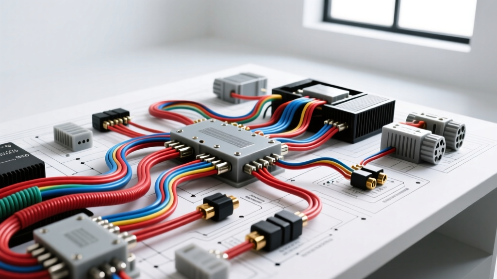
Technical Solution: The 12V DC Relay Isolation Diagram
To convert a PWM signal into a clean 12V DC trigger, a standard Bosch-style ISO 7588 relay must be implemented. This isolates the vehicle's sensitive lighting control module from the aftermarket camera.
| Relay Pin | Function | Connection Target | Wire Gauge |
|---|---|---|---|
| 86 | Coil Ground (-) | Vehicle Chassis Ground | 18 AWG |
| 85 | Coil Trigger (+) | Reverse Light PWM Signal (via Posi-Tap) | 22 AWG |
| 30 | Common / Load In | Clean 12V Switched (Ignition) or Constant | 18 AWG |
| 87 | Normally Open / Load Out | Camera 12V+ and Head Unit Reverse Trigger | 18 AWG |
Note: When utilizing a relay, the PWM signal from the reverse light only energizes the relay coil (Pin 85). The coil requires less than 150mA, which will not trip the vehicle's bulb-out CAN-bus sensors. The actual camera power is drawn from Pin 30, providing a flawless, uninterrupted 12V DC signal.
Video Signal Routing: Impedance and FAKRA Adapters
The physical routing of the video signal dictates the clarity of the image and the system's susceptibility to Electromagnetic Interference (EMI).
Coaxial Shielding and Routing Paths
Aftermarket cameras utilize a 75-ohm impedance RCA video cable. This cable must never be routed parallel to high-current wiring harnesses, fuel pump power lines, or ignition coil feeds. Routing the video cable down the passenger-side sill plate is the industry standard, as the driver-side harness typically houses high-speed CAN-bus lines and injector drivers that generate severe EMI.
FAKRA Z to RCA Integration
Modern factory and premium aftermarket head units (such as those from Pioneer, Kenwood, and Alpine) have largely abandoned standard RCA jacks for video inputs in favor of the FAKRA Z connector. The FAKRA Z is a shielded, impedance-matched coaxial connector designed to lock into the head unit, preventing vibration-induced signal loss. If your camera terminates in an RCA plug, a high-quality FAKRA Z-to-RCA female adapter with a molded strain-relief boot is mandatory to maintain the 75-ohm impedance across the connection point.
Retail vs. Custom 12V Integration Specifications
When evaluating the question "does Best Buy install backup cameras?", it is vital to understand the difference between a standard retail service and a custom mobile electronics integration. The table below outlines the technical divergence.
| Specification Parameter | Standard Retail Install (Baseline) | Custom 12V / MECP Certified Spec |
|---|---|---|
| Reverse Tap Method | Scotchlok / T-Tap (Pierces wire insulation) | Posi-Tap or Solder/Heat-Shrink (No copper exposure) |
| PWM Signal Handling | Direct tap (Risk of flickering/CAN errors) | Relay Isolation or dedicated PWM Rectifier Module |
| Video Cable Routing | Shortest path (Often alongside main harness) | Passenger-side dedicated routing, away from EMI |
| Wire Loom & Protection | Electrical tape wraps | Split-loom tubing and Tesa cloth tape (OEM style) |
| Ground Termination | Self-tapping screw into sheet metal | Ring terminal to existing OEM ground stud/bolt |
Authoritative References & Standards
Proper automotive electrical integration requires adherence to established engineering standards. The specifications outlined in this guide are derived from the following authoritative automotive electrical resources:
- SAE J1128 (Low Tension Primary Cable): Defines the thermal and mechanical requirements for automotive wiring, dictating why GXL or TXL 18 AWG wire must be used instead of standard PVC building wire. SAE International J1128 Standard.
- MECP (Mobile Electronics Certification Professional): The industry benchmark for 12V integration techniques, including proper relay pinout configurations, CAN-bus isolation, and EMI mitigation strategies for video routing. MECP Certification Guidelines.
- IPC/WHMA-A-620: The definitive standard for cable and wire harness assemblies, detailing the proper crimping and soldering techniques required for automotive sensor and camera power delivery.
Conclusion
While retail services provide an accessible entry point for aftermarket tech, understanding the underlying electrical architecture of your vehicle is paramount. Modern CAN-bus systems and PWM lighting circuits demand precise relay integration, proper impedance matching, and OEM-style wire looming. By applying these technical specifications, you ensure that your backup camera system operates flawlessly, free from digital noise, flickering, or vehicle computer faults.