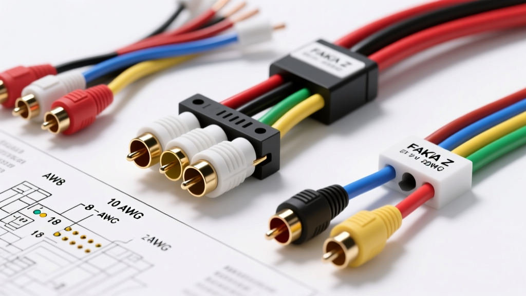
Selecting the Right Architecture: RCA vs. FAKRA Z
When integrating aftermarket vision systems into modern vehicles, selecting the correct hardware is only half the battle. The true challenge lies in interpreting and executing the correct reversing camera wiring diagram for your specific vehicle architecture. Automotive electrical systems have transitioned from simple 12V analog circuits to complex, multiplexed digital networks. Consequently, a one-size-fits-all approach to camera installation will inevitably lead to signal degradation, CANbus faults, or blown head unit LVDS transceivers.
This guide compares the two dominant reversing camera platforms—Analog Composite (RCA) and Digital LVDS (FAKRA Z)—providing the technical specifications, wire gauges, and pinout configurations required for a factory-grade installation. According to the SAE International Automotive Standards, understanding the impedance and signaling differences between these systems is critical for maintaining electromagnetic compatibility (EMC) within the vehicle cabin.
System Architecture Comparison Matrix
| Specification | Analog RCA (CVBS/AHD) | Digital FAKRA Z (LVDS) | Ethernet (IP/Camera-to-HU) |
|---|---|---|---|
| Signal Type | Single-Ended Analog (NTSC/PAL) | Low-Voltage Differential Signaling | TCP/IP over Shielded Twisted Pair |
| Impedance | 75-Ohm Coaxial | 100-Ohm Differential (Coax shielded) | 100-Ohm Differential |
| Connector Type | Standard RCA (Male/Female) | FAKRA Z (Water Blue Jacket) | H-MTD or MATEnet |
| Max Cable Run | 15 Meters (Unamplified) | 10 Meters (Strictly regulated) | 15+ Meters |
| Power Delivery | Separate 18 AWG (12V) | Separate or PoC (Power over Coax) | Power over Ethernet (PoE) |
Deep Dive: Analog RCA Reversing Camera Wiring Diagram
The analog RCA setup remains the most common aftermarket solution. A standard composite reversing camera wiring diagram relies on three primary circuit paths: the video signal, the camera power, and the head unit trigger. As detailed in Crutchfield's Backup Camera Installation Guide, improper grounding and PWM interference are the leading causes of failure in these systems.
Wire Gauge and Color Code Standards
- Video Signal (Center Conductor): 22-24 AWG stranded copper, typically enclosed in a yellow RCA jacket.
- Video Shield (Ground): Braided copper or spiral shield, tied to the RCA outer ring.
- Camera Power (+12V): 18 AWG, universally color-coded Red in aftermarket kits.
- Camera Ground: 18 AWG, universally color-coded Black.
- Reverse Trigger (To HU): 18-20 AWG, typically Green or White/Red stripe, carrying +12V to the head unit's reverse input wire.
The PWM Tail Light Problem and Filter Circuit
In vehicles manufactured post-2012 (particularly VW, Audi, BMW, and modern Ford models), the reverse lamp circuit is not a steady 12V DC source. The Body Control Module (BCM) uses Pulse Width Modulation (PWM) to monitor bulb health, rapidly switching the voltage on and off. If you tap an analog camera directly into a PWM reverse light, the camera will rapidly reboot, resulting in a flickering or blank display.
The Engineering Solution: You must install a PWM filter or DC-DC relay isolator. For a custom inline schematic, build a filter using:
- A 1N5408 Diode (3A, 1000V) placed in series with the +12V reverse tap (band facing the camera).
- A 2200µF 25V Electrolytic Capacitor placed in parallel across the camera's power and ground leads (observe strict polarity).
This RC-style filter smooths the PWM square wave into a steady 11.4V DC output, ensuring stable camera operation without triggering BCM open-circuit bulb-out warnings.
Deep Dive: Digital FAKRA Z Reversing Camera Wiring Diagram
When upgrading to high-definition AHD or 1080p digital systems, or retaining OEM cameras when swapping head units, the FAKRA Z connector is the industry standard. The FAKRA Z Standard Specifications dictate a water-blue plastic housing for LVDS video applications. Unlike RCA, FAKRA Z carries digital data, not an analog waveform.
LVDS Pinout and Impedance Matching
The FAKRA Z utilizes a single coaxial cable to transmit Low-Voltage Differential Signaling (LVDS). The wiring diagram for this system is deceptively simple but electrically unforgiving:
- Center Pin: LVDS Data + (Positive differential signal)
- Outer Shield: LVDS Data - (Negative differential signal / Signal Ground)
- Impedance: The entire cable run must maintain a strict 100-ohm differential impedance. Any sharp bends (under 30mm radius) or crimped sections will cause signal reflection and result in a "No Signal" or heavily artifacted display.
Powering the FAKRA Camera Head
Crucially, FAKRA Z cables do not carry power in standard automotive implementations (unless utilizing a proprietary Power-over-Coax adapter). The camera module requires a dedicated power source. However, while analog cameras require 12V, most OEM and high-end aftermarket LVDS camera sensors operate on 6V or 3.3V. Tapping a 12V reverse light directly into the camera's power pigtail will instantly destroy the internal LDO regulator and the LVDS transmitter IC.
Wiring Protocol: Use a dedicated 12V-to-6V buck converter (LDO) triggered by the reverse light circuit to supply the camera head. Ensure the buck converter is rated for at least 500mA to handle the inrush current of the camera's IR cut-filter solenoid when shifting into reverse.
Head Unit Triggering: Hardwire vs. CANbus Integration
A complete reversing camera wiring diagram must address how the head unit knows to switch to the camera input. There are two primary methods:
1. Analog Hardwire Trigger (Standard Aftermarket)
Most single-DIN and double-DIN aftermarket receivers feature a dedicated "Reverse" or "Back" wire (often Purple or Orange/White). This wire requires a +12V signal to activate the video switching relay inside the HU. You must run an 18 AWG wire from the vehicle's reverse lamp circuit (post-PWM filter) directly to this HU trigger wire. Grounding this wire or feeding it 5V will fail to trigger the display.
2. CANbus / Quadlock Integration (OEM & Premium Aftermarket)
In vehicles utilizing a CANbus gateway or OEM-style harnesses (like the VW Quadlock or BMW HSD), the reverse trigger is not a physical 12V wire. Instead, the Transmission Control Module (TCM) broadcasts a CAN message (e.g., CAN ID 0x351) indicating "Reverse Gear Engaged." The head unit reads this data packet on the CAN-H and CAN-L twisted pair (typically Pin 10 and Pin 11 on the Quadlock block) and internally switches the video input. In these scenarios, hardwiring a 12V trigger to the head unit's analog reverse wire will cause a conflict. You must use a CANbus interface module that translates the digital CAN message into a physical +12V output to trigger aftermarket screens.
Troubleshooting Matrix: Common Failure Modes
Even with a flawless wiring diagram execution, environmental factors and vehicle-specific quirks can cause issues. Use this diagnostic tree to isolate faults:
| Symptom | Probable Cause | Technical Fix |
|---|---|---|
| Rolling Horizontal Bars (Analog) | Ground Loop. The camera ground and HU ground are at different potentials, causing 60Hz alternator whine interference. | Isolate the RCA shield at the camera end using a ground loop isolator, or ensure the camera ground is tied to the exact same chassis bolt as the tail light ground. |
| Image Flickering / Rebooting | BCM PWM interference on the reverse light tap. | Install a 12V DC relay isolator or the 1N5408 / 2200µF capacitor filter circuit detailed above. |
| "No Signal" on FAKRA Z | Impedance mismatch, crushed coaxial cable, or missing 6V LDO power at the camera head. | Verify 100-ohm continuity. Check camera power pigtail with a multimeter (must read 5.8V - 6.2V). Replace FAKRA Z if outer shield is kinked. |
| Display Stays on in Drive | Trigger wire shorted to constant 12V, or CANbus module failing to send the "Park/Drive" state change. | Check HU trigger wire for backfeed from a shared accessory circuit. Ensure trigger wire is isolated on a dedicated relay. |
Final Installation Best Practices
When routing any video cable (RCA or FAKRA), maintain a minimum separation of 4 inches from high-current wiring harnesses, airbag modules, and ignition coils to prevent Electromagnetic Interference (EMI). Always use automotive-grade Tesa tape (fleece tape) to wrap your custom wiring looms, preventing rattles and protecting the 18 AWG trigger wires from chafing against the vehicle's sheet metal grommets when transitioning from the cabin into the trunk lid or liftgate. By strictly adhering to the correct reversing camera wiring diagram for your chosen architecture, you ensure a reliable, factory-style integration that withstands the harsh electrical environment of modern vehicles.