The Desert Environment: Why Standard Automotive Wiring Fails
When homeowners look for residential security camera installation Casa Grande AZ professionals, they are primarily concerned with Wi-Fi range, basic weatherproofing, and standard 120V AC power routing. However, automotive, fleet, and RV security camera installations in the Sonoran Desert demand an entirely different engineering approach. In Casa Grande, summer ambient temperatures routinely exceed 110°F (43°C). More importantly, the interior cavities of an RV, the undercarriage of a cargo van, or the attic space of a fifth wheel can easily reach 140°F to 160°F when parked in direct sunlight.
Standard PVC-jacketed automotive wire (rated for 105°C or lower) becomes brittle, and the insulation can melt or off-gas when routed near exhaust components or trapped in unventilated roof spaces. Furthermore, extreme UV exposure and thermal expansion/contraction cycles will destroy cheap crimp connectors, leading to voltage drops, video signal interference, and total camera failure. This complete wiring diagram walkthrough details how to properly spec, route, and terminate a heavy-duty 12V DC security camera system built specifically to survive extreme desert heat.
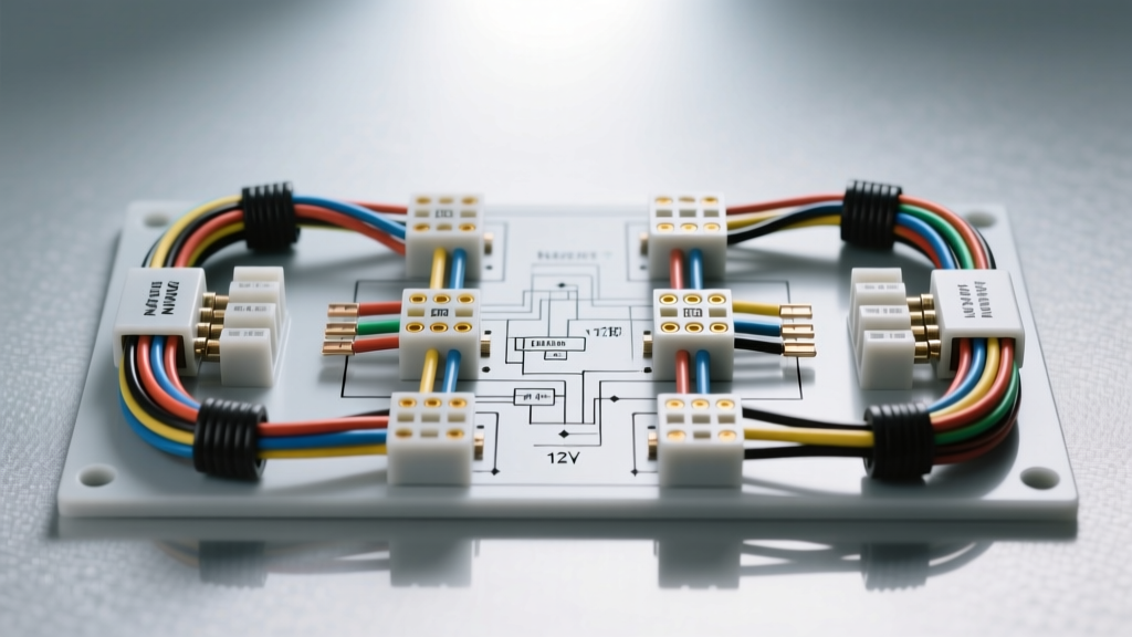
Core Wiring Diagram: M12 4-Pin IP67 Camera Harness
For heavy-duty automotive and RV applications, we bypass the standard 4-pin flat trailer connectors and consumer-grade RCA setups. Instead, we utilize an M12 4-Pin A-Coded waterproof connector. This industrial standard provides IP67 dust and water resistance and features threaded locking collars that vibrate loose far less often than push-fit alternatives.
Below is the definitive pinout and wire specification chart for a high-definition, heated observation/security camera system drawing a maximum of 2.0 Amps (including the internal defogging heater element).
| M12 Pin | Function | Wire Color | AWG Size | Jacket Material |
|---|---|---|---|---|
| Pin 1 | 12V DC+ (Constant or Switched) | Brown | 14 AWG | XLPE (125°C Rated) |
| Pin 2 | Video Signal (Analog/HD-CVI) | White | 18 AWG Shielded | PTFE / Teflon |
| Pin 3 | Reverse Trigger / Audio | Blue | 18 AWG | XLPE (125°C Rated) |
| Pin 4 | Ground (Chassis / DC-) | Black | 14 AWG | XLPE (125°C Rated) |
Material Science: XLPE vs. PVC in High Heat
Cross-linked polyethylene (XLPE) is mandatory for the power and ground legs in this environment. According to SAE J1128 standards for low-tension primary cables, XLPE offers superior thermal resistance and mechanical toughness compared to standard PVC. If your wire routing must pass within 6 inches of a catalytic converter or exhaust manifold, you must additionally wrap the harness in a high-temperature fiberglass or basalt sleeve rated for 1000°F.
Step-by-Step Routing and Harness Construction
A wiring diagram is only as good as its physical execution. Follow these steps to ensure the longevity of your camera harness:
- Harness Looming: Group the 14 AWG power/ground wires and the 18 AWG signal wires. Wrap them in split corrugated loom. Crucial: Do not use standard black electrical tape to seal the loom. The desert heat will melt the adhesive, creating a sticky mess that attracts dirt and eventually unravels. Use Tesa 51036 PET cloth tape, which is specifically designed for automotive engine bay and chassis wiring.
- Termination: Strip the wires using a precision thermal stripper if using PTFE shielded cable to avoid nicking the fine 18 AWG strands. Use closed-barrel, nylon-insulated crimps with an integrated heat shrink seal. Apply dual-wall adhesive-lined heat shrink (3M EPS300 or equivalent) over every termination. The inner adhesive layer melts and seals out moisture and corrosive desert dust.
- Chassis Pass-Throughs: Whenever the harness passes from the exterior into the cabin or cargo area, use a rubber grommet. Apply a liberal amount of dielectric grease inside the grommet to prevent the rubber from drying out, cracking, and allowing water ingress during the monsoon season.
- Grounding: Do not rely on sheet metal screws for the 14 AWG ground wire. Drill a 1/4-inch hole, clear away all paint and powder coating down to bare metal using a wire wheel, and secure the ring terminal with a stainless steel bolt, star washer, and nyloc nut. Coat the finished ground point in clear nail polish or liquid electrical tape to prevent oxidation.
Integrating the Reverse Trigger via Line Output Converter (LOC)
Modern vehicles, particularly late-model trucks and SUVs used as tow vehicles, no longer use simple 12V DC analog signals for reverse lights. They use Pulse Width Modulation (PWM) or CANbus-controlled lighting circuits. If you tap a PWM reverse light circuit directly into Pin 3 (Trigger) of your camera, the camera will flicker, fail to initialize, or trigger a dashboard 'bulb out' error code on the tow vehicle.
The Solution: Use an automotive Line Output Converter (LOC) or a dedicated PWM-to-DC relay bypass module.
- Tap the reverse light positive wire using a T-tap or, preferably, by soldering a jumper wire and sealing it with heat shrink.
- Feed this PWM signal into the input side of the LOC or smart relay module.
- The module will read the PWM frequency and output a clean, steady 12V DC+ signal.
- Route this clean 12V signal to Pin 3 of your camera harness, ensuring the camera switches on instantly and stably when the vehicle is shifted into reverse.
Voltage Drop Calculations for 40-Foot Runs
When wiring a security camera on the rear of a 40-foot motorhome or a long cargo trailer, voltage drop is a primary cause of poor night-vision performance (due to IR LED starvation). The ABYC E-11 standard, widely adopted as best practice for RV and marine 12V DC systems (referenced via RVIA technical guidelines), recommends a maximum 3% voltage drop for critical electronics.
The Math:
Camera Draw (with heater): 1.75 Amps
Total Wire Length (40 ft out + 40 ft back): 80 feet
14 AWG Copper Resistance: ~2.525 ohms per 1,000 feet
Total Resistance: (80 / 1000) * 2.525 = 0.202 ohms
Voltage Drop (V = I x R): 1.75A * 0.202 ohms = 0.35 Volts
With a 12.6V alternator output, the camera receives 12.25V. This is well within the 9V-16V operating range of most automotive cameras. If you were to use 18 AWG wire (40 feet round trip = 0.41 ohms resistance), the voltage drop would exceed 1.5 volts, potentially causing the camera's internal microprocessor to reset continuously when the IR LEDs engage at night.
Diagnostic Matrix: Troubleshooting Desert-Specific Failures
When a system fails in extreme heat, the root cause is often thermal. Use this diagnostic tree to isolate the issue:
- Symptom: Camera works in the morning, but displays 'No Signal' at 2:00 PM.
- Cause: Thermal expansion is pulling a poorly crimped pin out of the M12 connector, or the coaxial shielding inside the 18 AWG video wire is shorting against the power wire due to melted internal insulation.
- Fix: Perform a continuity test on the harness while applying a heat gun to the cable run. Replace the harness using PTFE-jacketed signal wire.
- Symptom: Video feed has severe static or rolling horizontal lines when the engine is running.
- Cause: Alternator whine (EMI/RFI interference) induced into the video signal wire, exacerbated by dry, dusty desert air reducing natural grounding conductivity, or routing the video wire parallel to high-current AC compressor cables.
- Fix: Ensure the 18 AWG video wire shield is grounded at the monitor side only to prevent a ground loop. Re-route the signal wire at least 6 inches away from any high-amperage 12V cables.
- Symptom: Camera lens is permanently fogged on the inside.
- Cause: Extreme temperature swings (115°F day to 75°F night) cause the internal air to contract, sucking moisture past a degraded O-ring seal. The internal desiccant pack is saturated.
- Fix: Open the camera housing in a low-humidity, air-conditioned environment. Replace the silica gel desiccant pack and reseal the housing using a continuous bead of marine-grade silicone (e.g., 3M 4200), avoiding the camera lens glass.
Final Inspection and Maintenance
Even the best security camera installation Casa Grande AZ setups require seasonal maintenance. Every six months, inspect the M12 connector threads for cross-threading or dust ingress. Apply a small dab of dielectric grease to the connector threads (not the pins) to ensure smooth mating and prevent galvanic corrosion between dissimilar metals. Verify your ground points for surface rust, and ensure all split loom remains securely fastened with UV-resistant PET tape. By adhering to these stringent automotive wiring standards, your vehicle's security and observation systems will remain operational through the harshest desert conditions.