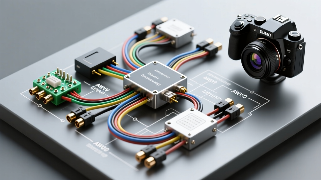
Introduction to Professional Auto Tech Standards
When evaluating a professional Geek Squad backup camera installation, the underlying electrical architecture must adhere to strict Mobile Electronics Certification Program (MECP) guidelines. Best Buy's Geek Squad Auto Technicians are trained to bypass amateur wiring practices, ensuring that aftermarket CMOS and CCD camera systems integrate seamlessly with modern vehicle CAN-bus networks and infotainment head units. This technical specification reference outlines the precise wire gauges, pin configurations, reverse trigger filtering circuits, and RCA impedance requirements necessary for a factory-grade backup camera deployment.
Camera Sensor and Video Output Specifications
Aftermarket backup cameras generally utilize either CMOS (Complementary Metal-Oxide-Semiconductor) or CCD (Charge-Coupled Device) sensors. While CCD sensors offer superior low-light performance and dynamic range, modern CMOS sensors with wide dynamic range (WDR) processing have become the industry standard due to lower power consumption and cost. The video signal is transmitted via an analog composite RCA connection.
| Specification | CMOS Standard | CCD High-Performance |
|---|---|---|
| Operating Voltage | 3.3V - 5V DC (Internal Regulator) | 5V - 12V DC |
| Current Draw | 80mA - 120mA | 150mA - 250mA |
| Video Output Format | NTSC / PAL (Switchable) | NTSC (720x480) / PAL (720x576) |
| Output Impedance | 75-Ohm Composite | 75-Ohm Composite |
| Signal-to-Noise Ratio | ≥ 48 dB | ≥ 52 dB |
Standard 4-Pin Camera Wiring Harness Breakdown
Most license-plate-mounted and flush-mount aftermarket cameras utilize a standardized 4-pin Molex or JST connector at the camera head, which adapts to a multi-cable RCA harness. Understanding this pinout is critical for diagnosing signal loss or power faults during a Geek Squad backup camera installation.
- Pin 1 (Red): 12V+ DC Power Input. Requires a stable 12V source, typically tapped from the reverse lamp circuit or a dedicated fuse box add-a-circuit.
- Pin 2 (Black): Chassis Ground. Must be terminated to a clean, unpainted metal surface using a ring terminal and self-tapping screw, or spliced into a verified OEM ground wire.
- Pin 3 (Yellow/White RCA): Composite Video Signal Center Conductor. Carries the 1V peak-to-peak analog video signal.
- Pin 4 (Shield/Bare): RCA Shield Ground. Completes the 75-ohm circuit and protects against electromagnetic interference (EMI).
Power Delivery and Fusing Requirements
Professional installers strictly adhere to AWG (American Wire Gauge) standards to prevent voltage drop. For a standard backup camera drawing less than 250mA, 18 AWG primary wire is the minimum requirement for power and ground runs up to 15 feet. If the camera includes integrated LED floodlights or a heated lens element, the current draw may exceed 1A, necessitating an upgrade to 16 AWG wire.
Every Geek Squad backup camera installation requires inline overcurrent protection. A 3A ATC or AGC blade fuse must be installed on the 12V+ power lead within 6 inches of the tap point. This prevents catastrophic harness melting in the event of a short circuit within the camera housing or RCA barrel connector.
The Reverse Trigger Circuit: Navigating CAN-Bus and PWM
The most complex aspect of modern camera integration is the reverse trigger signal. The head unit requires a +12V signal on its dedicated reverse trigger wire (usually purple or orange/white) to switch the display to the camera input. However, modern vehicles utilize Pulse Width Modulation (PWM) and multiplexed CAN-bus systems to control exterior lighting.
The PWM Filtering Problem
If you tap a PWM-controlled reverse light directly, the camera will flicker, drop out, or fail to power on, and the head unit will rapidly cycle between audio and video modes. To resolve this, technicians must deploy a PWM filter circuit or a relay isolation module.
Capacitor and Diode Filter Circuit
A passive filter can be constructed using a 1N4004 rectifier diode and a 1000µF 16V electrolytic capacitor. The diode is placed in series with the 12V+ tap (stripe facing the camera) to prevent backfeeding, while the capacitor is wired in parallel across the camera's power and ground to smooth the PWM pulses into a steady DC voltage.
Bosch ISO Mini Relay Isolation
For high-current or highly sensitive CAN-bus systems, a standard 5-pin automotive relay (Bosch ISO mini format) is the preferred MECP-compliant solution:
- Pin 86: Tapped to the OEM reverse light positive wire (Trigger).
- Pin 85: Chassis Ground.
- Pin 30: Constant 12V+ from an accessory fuse (Add-a-Circuit).
- Pin 87: Output to the Camera 12V+ and Head Unit Reverse Trigger.
This setup ensures the camera receives clean, uninterrupted 12V DC power while drawing virtually zero current from the vehicle's sensitive lighting control module.
RCA Video Signal Routing and Shielding
According to SAE J1113 standards for electromagnetic compatibility, analog composite video signals are highly susceptible to radiated emissions. The RCA cable must never be routed parallel to high-current power wires, amplifiers, or ignition coil harnesses. Maintain a minimum separation of 12 inches between the RCA video cable and any 12V+ power cables. If crossing is unavoidable, the cables must intersect at a strict 90-degree angle to minimize inductive coupling, which manifests as alternator whine or rolling horizontal bars on the head unit display.
MECP-Compliant Connection Methods
A hallmark of a genuine Geek Squad backup camera installation is the complete absence of "scotch locks" or T-taps. These piercing connectors oxidize over time, leading to high-resistance joints and intermittent camera failures. As outlined in the MECP installation guidelines, all wire splices must be executed using one of the following methods:
- Solder and Heat Shrink: The gold standard. Wires are twisted, soldered with rosin-core solder, and sealed with adhesive-lined marine heat shrink.
- Military Splice: Wires are woven through each other, soldered, and sealed.
- Posi-Taps: Threaded, non-destructive tap connectors that clamp around the OEM wire without severing the copper strands, sealed with dielectric grease.
Diagnostic Troubleshooting Matrix
When a camera system fails post-installation, technicians utilize a systematic diagnostic approach. The Crutchfield car audio wiring archives and OEM service manuals provide the foundational logic for the following troubleshooting matrix:
| Symptom | Root Cause Analysis | Technical Resolution |
|---|---|---|
| Camera image flickers rapidly | PWM signal from taillight circuit; insufficient DC smoothing. | Install 1N4004 diode and 1000µF capacitor, or use a 5-pin relay isolation. |
| Head unit displays "No Signal" | RCA center pin not seating; reverse trigger wire not receiving 12V. | Verify RCA impedance continuity; test head unit trigger wire with a digital multimeter. |
| Rolling horizontal bars on screen | Ground loop or EMI from alternator; RCA routed near power wires. | Verify camera ground is on bare metal; reroute RCA away from harness; check RCA shield continuity. |
| Camera powers on but image is black | NTSC/PAL mismatch between camera and head unit; blown internal CMOS regulator. | Toggle camera NTSC/PAL loop wire; verify 5V output at camera sensor board. |
| Delayed camera shut-off | Vehicle retains reverse light power via BCM delay or capacitor in taillight circuit. | Install a 100-ohm bleeder resistor in parallel with the camera power wire to drain residual voltage. |
Conclusion
Executing a flawless Geek Squad backup camera installation requires far more than simply connecting red to red and black to black. By adhering to strict AWG sizing, implementing PWM filtering for modern CAN-bus vehicles, ensuring 75-ohm RCA impedance integrity, and utilizing MECP-approved soldering techniques, technicians can deliver a reliable, factory-integrated reverse camera system that withstands the harsh electrical and environmental conditions of the modern automobile.