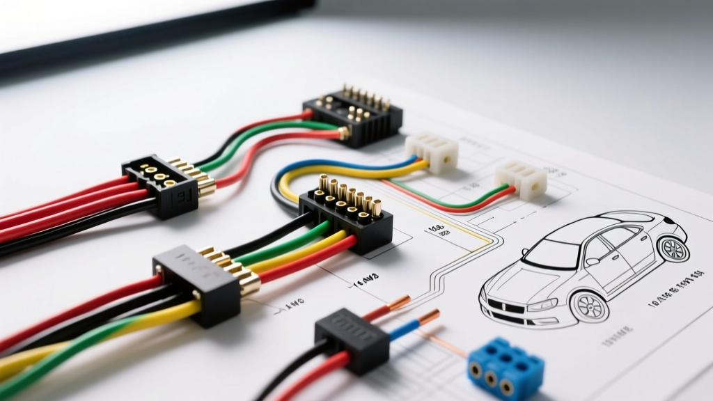
Introduction to Metra Active LOCs in Tech Integration
Integrating aftermarket camera systems, DSPs, and video interface modules into modern factory infotainment networks requires precise signal extraction. The Metra Active Line Output Converter (LOC) series is engineered to sum, flatten, and convert high-level factory speaker outputs into clean, low-level RCA signals. While primarily used for amplifier integration, a properly configured Metra LOC is critical in advanced camera and tech installations where an aftermarket video interface or DSP requires a flat analog audio reference to process parking sensor chimes and backup camera audio overlays without triggering factory impedance faults.
This technical specification reference details the exact Metra LOC wiring diagram, pinout configurations, 18 AWG wire color codes, and signal-sensing thresholds required for seamless integration with backup camera trigger circuits and digital signal processors.
Metra LOC Wiring Diagram: Core Pinout & Wire Color Codes
The standard Metra active LOC harness utilizes 18 AWG stranded copper wire, compliant with SAE J1128 low-tension primary cable specifications. The inputs are designed to handle factory amplified signals up to 40V peak-to-peak, while the outputs provide a regulated low-level signal (typically up to 5V RMS) suitable for DSPs and camera interface modules.
| Wire Color | Function | AWG | Connection Target |
|---|---|---|---|
| Red | +12V Constant Power | 18 | Vehicle Battery / Constant 12V Source |
| Black | Chassis Ground | 18 | Bare Metal Chassis (Ring Terminal) |
| Blue/White | Remote Turn-On Output / Signal Sense | 18 | DSP Remote In / Camera Interface Trigger |
| White | Left Front (+) | 18 | Factory LF Speaker Wire (+) |
| White/Black | Left Front (-) | 18 | Factory LF Speaker Wire (-) |
| Gray | Right Front (+) | 18 | Factory RF Speaker Wire (+) |
| Gray/Black | Right Front (-) | 18 | Factory RF Speaker Wire (-) |
| Green | Left Rear (+) | 18 | Factory LR Speaker Wire (+) |
| Green/Black | Left Rear (-) | 18 | Factory LR Speaker Wire (-) |
| Purple | Right Rear (+) | 18 | Factory RR Speaker Wire (+) |
| Purple/Black | Right Rear (-) | 18 | Factory RR Speaker Wire (-) |
Signal Sensing vs. 12V Remote Turn-On Configuration
In modern camera and tech installations, the factory head unit rarely provides a traditional +12V remote turn-on wire. Instead, audio is transmitted via CAN-bus or A2B (Automotive Audio Bus) networks. The Metra LOC utilizes an internal Audio Signal Sensing circuit on the Blue/White wire to detect AC voltage on the speaker inputs and generate a +12V remote output.
Configuring for Camera Trigger & DSP Integration
When integrating a backup camera interface that requires an audio reference to mix parking proximity chimes with the camera video feed, the LOC's signal sense circuit must be calibrated. The internal threshold is typically set to trigger at >2.5V AC. If the factory radio uses aggressive volume-dependent EQ or active noise cancellation (ANC), the LOC may misinterpret ANC microphone feedback as an audio signal, causing the camera interface to power cycle erratically.
- Dip Switch Configuration: Set the internal summing switches to "ON" for Front and Rear inputs if the factory system uses a dedicated center channel or subwoofer that carries the parking chime frequencies (typically 800Hz - 2kHz).
- Output Level Calibration: Using a digital multimeter (DMM) set to AC Voltage, play a 1kHz test tone at 75% volume. Adjust the LOC's internal gain potentiometers until the RCA outputs read exactly 2.0V to 4.0V RMS. Exceeding 5V RMS will clip the input stage of most camera interface modules.
Load Resistor Specifications & Impedance Matching
Many late-model vehicles (e.g., GM Bose, Ford Sony, Chrysler Alpine systems) utilize Class-D factory amplifiers with integrated diagnostic routines. If the Metra LOC is tapped directly into the speaker wires and the physical speakers are removed or bypassed, the factory amp will detect an open circuit (infinite impedance) and shut down the audio channels, resulting in zero signal to the LOC and a complete failure of the camera chime integration.
Parallel Load Resistor Wiring
To maintain the required 2-ohm or 4-ohm load, you must install load resistors in parallel with the LOC's high-level inputs. According to Metra Electronics technical bulletins, when tapping a 4-ohm factory speaker circuit to feed the high-impedance input of an active LOC, a 10-ohm, 50-watt aluminum-housed resistor should be wired in parallel across the (+) and (-) input wires of the LOC.
Warning: Load resistors generate extreme heat. They must be mounted to a bare metal chassis surface using stainless steel hardware, never zip-tied to plastic trim or existing wiring harnesses.
Troubleshooting Common LOC & Camera Signal Failures
When integrating complex camera systems with active LOCs, voltage drops and ground loops are the primary culprits for signal degradation. Below is a diagnostic decision tree for resolving installation faults.
Decision Tree: No Remote Turn-On / Camera Trigger Failure
- Symptom: Camera interface does not power on in reverse; LOC Blue/White wire reads 0V.
- Check 1: Measure +12V Constant at the Red wire with a DMM. If <11.5V, repair power feed.
- Check 2: Measure Ground at the Black wire. Perform a voltage drop test under load. If voltage drop exceeds 0.1V, clean chassis ground point and re-terminate with a closed-loop ring terminal.
- Check 3: Verify AC signal presence at the White/Gray inputs while the radio is on. If 0V AC, the factory amplifier may be in protection mode due to missing load resistors.
- Check 4: If factory ANC is active, the LOC may be false-triggering or failing to latch. Disable ANC via factory diagnostic tool or physically disconnect ANC microphones before the LOC inputs.
Eliminating Ground Loop Whine in Camera Audio Overlays
If a high-pitched alternator whine is introduced into the cabin only when the backup camera is engaged and the LOC is feeding the DSP, you are experiencing a ground loop. This occurs when the LOC's ground potential differs from the camera interface module's ground potential. To resolve this, ensure both the Metra LOC and the camera video interface are grounded to the same physical chassis bolt, utilizing identical gauge wire (18 AWG) to maintain equipotential grounding. For persistent noise, install a 12V DC ground loop isolator on the +12V trigger feed to the camera module, referencing Crutchfield's alternator noise elimination guidelines.
By strictly adhering to these pinout specifications, AWG requirements, and impedance matching protocols, installers can ensure that the Metra LOC provides a flawless, noise-free audio foundation for advanced DSP and backup camera tech integrations.