Architecting a 4-Channel Vehicle Surveillance System
Executing a comprehensive DIY surveillance camera installation on a Class C RV, overland expedition truck, or commercial fleet vehicle requires moving beyond simple single-lens backup cameras. Modern large-footprint vehicles demand a 360-degree bird’s-eye view or a 4-channel AHD (Analog High Definition) 1080p multiplexer system to eliminate blind spots. Unlike standard consumer setups, an advanced automotive surveillance architecture must withstand severe voltage transients, high-frequency electromagnetic interference (EMI) from alternators and inverters, and extreme thermal cycling.
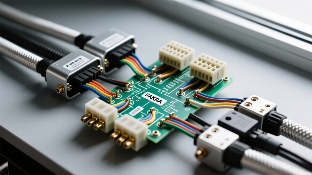
This technical deep dive explores the electrical topology required to integrate a 4-channel AHD multiplexer hub, focusing on power distribution calculations, FAKRA Z coaxial routing, and Body Control Module (BCM) trigger isolation. Whether you are wiring a 40-foot motorhome or a custom Sprinter van build, understanding the underlying electrical principles is critical to preventing signal degradation and module failure.
Connector Selection: FAKRA Z vs. M12 D-Coded vs. RCA
The most common point of failure in any aftermarket camera system is the video interconnect. Standard RCA connectors are entirely unsuited for mobile surveillance applications due to their lack of locking mechanisms, poor impedance matching, and zero environmental sealing.
- FAKRA Z Connectors: The automotive industry standard for coaxial video. FAKRA Z provides a 50-ohm impedance match, a locking housing that prevents vibration-induced disconnects, and color-coded keys (Z-code is universally reserved for analog/AHD video). For AHD 1080p systems running at 25/30fps, FAKRA Z paired with RG-174 or RG-59/U shielded coaxial cable is mandatory.
- M12 D-Coded Connectors: If your DIY surveillance camera installation utilizes IP-based digital cameras (Ethernet over coax or twisted pair), M12 D-coded connectors offer IP67 waterproofing and robust EMI shielding. However, they require specialized crimping tools and PoE (Power over Ethernet) injectors.
- Power & Control Harnesses: For the multiplexer hub power and trigger inputs, utilize sealed TE Connectivity Superseal 1.5 or Deutsch DT series connectors to ensure moisture ingress protection in the engine bay or exterior chassis mounting points.
Power Distribution & Voltage Drop Calculations
A 4-channel AHD multiplexer and four infrared-equipped cameras can draw a combined peak current of 4.5A to 5.5A (especially during night vision activation when IR LEDs engage). Routing power from the front chassis battery to a rear-mounted multiplexer in a 35-foot RV requires strict adherence to SAE J1128 low-tension primary cable standards to prevent excessive voltage drop.
Voltage Drop Calculation Example
Let us calculate the voltage drop for a 35-foot cable run (70 feet total round-trip for positive and ground) powering a 4.5A load using 14 AWG copper wire.
- Wire Resistance: 14 AWG stranded copper has a resistance of approximately 2.525 ohms per 1,000 feet.
- Total Circuit Resistance: (70 ft / 1000) * 2.525 ohms = 0.1767 ohms.
- Voltage Drop (V = I × R): 4.5A × 0.1767 ohms = 0.795V.
- Terminal Voltage: Assuming a resting battery voltage of 12.8V, the voltage at the multiplexer will be 12.00V.
A terminal voltage of 12.00V is well within the operational tolerance of automotive AHD multiplexers (typically 9V–16V). However, if you were to use 18 AWG wire for this run, the voltage drop would exceed 2.0V, potentially causing the IR LEDs to flicker or the multiplexer to reboot during engine cranking transients. Always use a minimum of 14 AWG SAE J1128 primary wire for the main multiplexer power feed, protected by an inline 10A MAXI fuse located within 18 inches of the battery positive terminal.
12-Pin Multiplexer Harness Pinout Matrix
Most heavy-duty 4-channel multiplexers utilize a 12-pin or 16-pin sealed harness for power, ground, and directional triggers. Below is the standard wiring matrix for a generic 12-pin AHD surveillance hub. Always cross-reference with your specific manufacturer's schematic.
| Pin | Wire Color | Function | AWG Size | Notes / Integration Point |
|---|---|---|---|---|
| 1 | Red | +12V Constant (B+) | 14 AWG | Direct to battery via 10A fuse. Maintains DVR recording. |
| 2 | Yellow | +12V Ignition (ACC) | 16 AWG | Fuse box ACC tap. Wakes the display monitor. |
| 3 | Purple | Reverse Trigger | 18 AWG | Requires PWM filter on modern CAN-bus vehicles. |
| 4 | Green | Left Turn Trigger | 18 AWG | Triggers left-side blind-spot camera overlay. |
| 5 | White | Right Turn Trigger | 18 AWG | Triggers right-side blind-spot camera overlay. |
| 6 | Black/Red | Camera 1 Video Ground | N/A (Coax) | FAKRA Z outer shield. |
| 7 | Black/Yel | Camera 2 Video Ground | N/A (Coax) | FAKRA Z outer shield. |
| 8 | Black/Grn | Camera 3 Video Ground | N/A (Coax) | FAKRA Z outer shield. |
| 9 | Black/Wht | Camera 4 Video Ground | N/A (Coax) | FAKRA Z outer shield. |
| 10 | Black | Main Chassis Ground | 14 AWG | Must be star-grounded to bare chassis metal. |
| 11 | Orange | CAN-H (Reserved) | 22 AWG | For J1939 integration on commercial trucks. |
| 12 | Orange/Blk | CAN-L (Reserved) | 22 AWG | For J1939 integration on commercial trucks. |
Trigger Integration: The PWM Lighting Problem
One of the most significant hurdles in a modern DIY surveillance camera installation is acquiring a clean reverse trigger signal. Vehicles manufactured after 2015 rarely use simple 12V analog switches for lighting. Instead, the Body Control Module (BCM) drives the reverse lamps using Pulse Width Modulation (PWM) to monitor bulb health and detect outages.
If you tap directly into a PWM-controlled reverse wire and feed it into Pin 3 of your multiplexer, the multiplexer will interpret the rapid on/off pulsing as a strobing trigger. This results in the surveillance monitor rapidly switching between the 4-channel grid view and the single reverse-camera view, rendering the system unusable.
Solution: PWM-to-DC Relay Isolation
To resolve this, you must isolate the BCM circuit using a standard 30A automotive SPDT relay and a diode:
- Tap the BCM reverse wire and connect it to the relay coil (Pin 86).
- Connect the relay coil ground (Pin 85) to chassis ground.
- Wire a 1N4007 flyback diode across Pins 85 and 86 (stripe facing 86) to suppress inductive voltage spikes that could damage the BCM.
- Connect a clean, fused +12V constant source to the relay Common (Pin 30).
- Connect the relay Normally Open (Pin 87) to the Purple trigger wire on the multiplexer.
Alternatively, use a dedicated automotive PWM-to-DC filter module, which utilizes a capacitor-resistor network to smooth the PWM signal into a flat 12V DC output without the mechanical clicking of a relay.
Coaxial Routing, Bend Radius, and EMI Shielding
Video signal degradation in mobile surveillance systems is almost always a result of poor coaxial cable management. AHD 1080p signals operate at high frequencies (typically around 74.25 MHz for 1080p30). At these frequencies, the coaxial shield is the only barrier against alternator whine and ignition coil EMI.
- Bend Radius: Never sharply crease RG-59/U or RG-174 coaxial cable. The minimum bend radius must not exceed 10 times the outer diameter of the cable. A sharp 90-degree fold will fracture the internal braided shield and alter the 50-ohm impedance, causing ghosting or complete signal loss.
- Separation from AC Inverters: Route all FAKRA video harnesses at least 12 inches away from high-current DC-to-AC inverters and microwave oven power feeds. The high-frequency switching noise from cheap modified-sine-wave inverters will easily penetrate poorly shielded RCA cables, though FAKRA Z provides superior rejection.
- Drip Loops: When routing the FAKRA cable from an exterior-mounted camera through the chassis or roof gland, always form a 'drip loop' below the entry point. This prevents capillary action from drawing water along the cable jacket directly into the multiplexer housing.
Grounding Topology: Star vs. Daisy Chain
A frequent mistake in multi-camera installations is daisy-chaining the camera grounds (connecting Camera 1 ground to Camera 2 ground, and so on, before returning to the chassis). This creates a ground loop. When the IR LEDs on Camera 1 activate, the increased current flow raises the ground potential for Camera 2, resulting in horizontal rolling bars (sync hum) on the secondary camera feeds.
The Fix: Implement a strict star grounding topology. Every camera's power ground and the multiplexer's main ground (Pin 10) must have their own dedicated wire routed to a single, centralized brass grounding bus bar. The bus bar must be bolted to bare, unpainted chassis steel using a star washer to bite through any corrosion or zinc plating, ensuring a zero-impedance path back to the battery negative terminal.
Troubleshooting Decision Tree: Signal & Power Failures
When your DIY surveillance camera installation exhibits faults, use this systematic decision tree to isolate the failure mode:
- Symptom: Monitor displays 'No Signal' on all 4 channels.
Cause: Multiplexer has lost main ground or constant 12V power.
Fix: Check the 10A inline MAXI fuse near the battery. Verify continuity between Pin 10 (Black) and the battery negative terminal using a multimeter. Resistance should be less than 0.5 ohms. - Symptom: Severe horizontal rolling bars on the display at night.
Cause: Ground loop or voltage drop during IR LED engagement.
Fix: Measure DC voltage at the camera pigtail while the IR LEDs are active. If voltage drops below 11.5V, upgrade the camera power feed from 18 AWG to 16 AWG. Ensure star grounding is implemented. - Symptom: Video feed randomly freezes or shows digital artifacting.
Cause: EMI interference or damaged FAKRA Z center pin.
Fix: Inspect the FAKRA connectors for pushed-back center pins (a common issue if the connector was forced without aligning the Z-key). Ensure video cables are not zip-tied parallel to the vehicle's main alternator charging wire. - Symptom: Reverse trigger strobes or fails to engage the rear camera.
Cause: BCM PWM signal detected without filtration.
Fix: Install a PWM-to-DC filter module or a relay isolation circuit between the vehicle's reverse lamp wire and the multiplexer's Purple trigger wire.
By adhering to these advanced electrical standards and utilizing proper automotive-grade interconnects, your multi-camera surveillance system will deliver flawless, broadcast-quality video regardless of the environmental conditions or vehicle size.