Introduction to Western Plow Electrical Systems
For new plow operators and fleet technicians alike, understanding the western plow wiring harness is the first step toward reliable winter operations. Unlike older, direct-wire relay systems that required a tangled web of heavy-gauge copper to operate every individual solenoid and headlight, modern Western systems utilize advanced multiplexing technology. This beginner-friendly guide breaks down the fundamentals of the Western Fleet-Flex architecture, detailing wire specifications, connector pinouts, routing best practices, and common failure modes so you can maintain your equipment with confidence.
Understanding the Fleet-Flex Multiplex Architecture
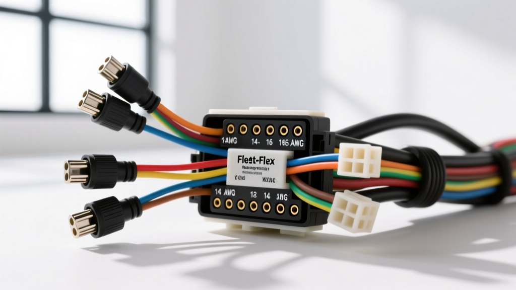
The cornerstone of modern Western electrical systems is the Fleet-Flex harness. The primary advantage of this system is interchangeability: a single truck-side harness and controller can operate multiple types of plows (such as the Ultramount, Pro-Tech, or Wide-Out) simply by plugging them in.
This is achieved through multiplexing. Instead of sending 12-volt power down a dedicated wire for every single function (e.g., lift, drop, angle left, angle right, high beams), the truck-side control module sends digital data signals over a pair of communication wires. The plow-side receiver node decodes these signals and triggers the appropriate high-amperage solenoids or relays locally on the plow. This drastically reduces the number of wires crossing the grille, minimizing voltage drop and reducing the physical weight and stiffness of the harness in sub-zero temperatures.
The Evolution: 11-Pin vs. 13-Pin Connectors
If you are working on older Western setups (pre-2010s), you may encounter the legacy 11-pin connector or the older dual 4-pin/7-pin setups. However, the current industry standard for the western plow wiring harness is the 13-pin Fleet-Flex connector. This circular, weather-sealed connector handles both the heavy amperage required for the main hydraulic pump motor and the low-voltage multiplex data signals simultaneously. It features a threaded locking ring to ensure a watertight seal and prevent vibration-induced disconnects on rough, unplowed roads.
Wire Color Codes and Pinout Specifications
When diagnosing or repairing a western plow wiring harness, referencing the correct pinout is critical. Below is the standard reference chart for the modern 13-pin Fleet-Flex truck-to-plow connection. Always verify against the specific schematic for your model year, as minor revisions occur.
| Pin | Wire Color | Function / Signal | AWG Size | Circuit Type |
|---|---|---|---|---|
| A | Black | Main System Ground | 10 AWG | High Current |
| B | Red | Main Battery Power (Switched) | 10 AWG | High Current |
| C | White | Multiplex Communication A (+) | 18 AWG | Data / Signal |
| D | Green | Multiplex Communication B (-) | 18 AWG | Data / Signal |
| E | Brown | Parking / Marker Lights | 16 AWG | Lighting |
| F | Dark Blue | Right Turn / Hazard | 16 AWG | Lighting |
| G | Light Blue | Left Turn / Hazard | 16 AWG | Lighting |
| H | Yellow | High Beam Headlights | 14 AWG | Lighting |
| J | Purple | Low Beam Headlights | 14 AWG | Lighting |
| K | Orange | Controller Wake / Ignition Sense | 18 AWG | Signal |
Note: Pins L and M are often reserved for auxiliary functions or future firmware expansions depending on the specific isolation module installed.
AWG Sizing and SAE Insulation Standards
One of the most common beginner mistakes is using standard hardware-store wire to repair a damaged harness. According to the SAE J1128 Low Tension Primary Cable Standard, automotive wire must withstand extreme temperature fluctuations, chemical exposure (road salt, oil), and physical abrasion.
Standard PVC-insulated wire becomes brittle and cracks when flexed at -20°F. A proper western plow wiring harness utilizes Cross-Linked Polyethylene (XLPE) insulation, often designated as SXL, GXL, or TXL wire. TXL (Thin-wall) is preferred for its flexibility and lighter weight, which is crucial for a harness that must drape across the front of a truck and bend when the plow angles. Never use THHN building wire or standard stranded copper for plow harness repairs; it will fail prematurely and risk a short circuit.
Routing and Securing the Truck-Side Harness
Proper routing ensures the longevity of your harness. The truck-side harness must be routed from the battery and firewall to the front grille without interfering with moving components or heat sources.
- Firewall to Engine Bay: Route the harness through an existing rubber grommet. If drilling a new hole is required, use a step-bit and install a new rubber grommet to prevent the sheet metal from slicing the wire insulation.
- Avoiding Heat and Moving Parts: Keep the harness at least 6 inches away from exhaust manifolds and turbochargers. Secure the harness away from the steering shaft, fan belts, and the radiator fan shroud using UV-resistant zip ties and P-clamps.
- Grille Drop: The harness should exit the grille in a location that provides a natural drip loop. This prevents water from wicking down the wires and into the connector housing. Wrap the final 24 inches of the harness in split-loom tubing and secure it with adhesive-lined heat shrink to prevent saltwater intrusion.
Power, Ground, and Torque Specifications
The main power and ground circuits (Pins A and B, along with the direct battery cables) carry the brunt of the electrical load, often exceeding 80 amps when the hydraulic pump motor is under heavy load (such as lifting a fully loaded, ice-caked plow).
- Wire Gauge: Use a minimum of 8 AWG or 10 AWG SXL wire for the main battery feeds.
- Terminals: Use closed-ring, heat-shrink terminals. Avoid open-spade terminals which can slip off the battery stud.
- Torque Specs: When attaching to a standard 3/8-inch battery terminal stud, torque the nut to 10-12 ft-lbs (120-144 in-lbs). Over-tightening can strip the lead threads of the battery post; under-tightening causes high resistance and voltage drop.
- Corrosion Prevention: Apply a conductive anti-oxidant paste (like No-Ox-Id) to the terminal faces before tightening, and coat the exterior with a dielectric battery spray to prevent galvanic corrosion from road salt.
Common Beginner Mistakes and Failure Modes
When troubleshooting a western plow wiring harness, beginners often assume the hydraulic pump or the controller is bad when the issue is actually a simple wiring fault. Use this decision tree to diagnose common issues:
Symptom: Controller Powers On, But Plow Does Not Move
- Cause 1: Blown Main Inline Mega Fuse (usually 150A). Fix: Inspect the fuse located near the battery. If blown, check for a seized hydraulic pump or pinched main power wire before replacing.
- Cause 2: Poor Ground Connection at the engine block. Fix: The plow ground must tie into the engine block or chassis ground, not just the battery negative. Clean the mounting surface to bare metal and re-secure.
Symptom: Erratic Plow Movement or Flashing Controller Codes
- Cause 1: Data Line Interference. Fix: Ensure the Multiplex Communication wires (White and Green) are not routed parallel to high-tension ignition wires or aftermarket LED light bar power feeds, which can induce electromagnetic interference (EMI).
- Cause 2: Moisture in the 13-Pin Connector. Fix: Disconnect the grille plug, inspect for green/white corrosion on the pins, clean with electrical contact cleaner, and pack the connector with a high-quality silicone dielectric grease (such as Nyogel 760G) to displace moisture.
Authoritative Resources and Further Reading
To continue your education on snow plow electrical systems, always refer to manufacturer documentation and established industry standards. We recommend bookmarking the Western Plows Tech Library for the most up-to-date schematics, isolation module flash procedures, and multiplex controller code definitions. Additionally, distributors like Central Parts Warehouse offer excellent technical guides and cross-reference charts for matching truck-specific headlamp harness adapters to your exact vehicle make and model.
By respecting the engineering behind the Fleet-Flex system, using the correct SAE-rated materials, and following proper routing and termination procedures, you will ensure your western plow wiring harness survives the harshest winter conditions without fail.