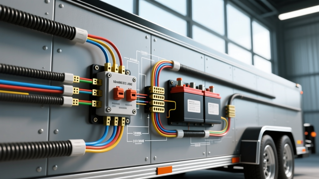
Understanding the 4 Way Electrical Switch in 12V DC Trailer Architecture
When automotive electricians and custom trailer builders reference a 4 way electrical switch wiring diagram, they are rarely discussing residential AC light switches. In the context of heavy-duty car haulers, overland campers, and enclosed toy haulers, a '4-way switch' refers to a high-amperage, 4-position DC rotary selector switch (commonly configured as 1-2-BOTH-OFF). This component is the beating heart of a dual-battery trailer management system, allowing operators to isolate a chassis/winch battery from a house/accessory battery, combine them for emergency winching, or disconnect all loads during long-term storage.
Designing a robust 12V DC architecture around a heavy-duty rotary switch requires strict adherence to SAE cable standards, precise terminal crimping, and an understanding of voltage drop under extreme inductive loads. A standard car hauler winch can pull 12,000 lbs, drawing upwards of 350 to 450 amps under peak stall conditions. If your 4 way electrical switch wiring diagram is executed with undersized cabling or improper terminal torque, the resulting thermal runaway will melt insulation and cause catastrophic electrical fires.
Integrating the Tow Vehicle 7-Way Connector
Before routing cables to the rotary switch, you must establish the charge line from the tow vehicle. The standard 7-way RV blade connector provides a dedicated 12V auxiliary feed that is critical for maintaining trailer batteries on long hauls. Understanding the 7-pin layout is mandatory for proper integration with your battery isolator switch.
- Pin 1 (Yellow): Left Turn / Brake
- Pin 2 (Blue): Reverse Lights / Electric Reverse Lockout
- Pin 3 (White): System Ground (Must be 8 AWG or larger, bonded to chassis)
- Pin 4 (Black): 12V Auxiliary / Battery Charge Feed (Typically 10 AWG or 8 AWG)
- Pin 5 (Green): Right Turn / Brake
- Pin 6 (Red/Brown): Electric Trailer Brakes
- Pin 7 (Brown): Running / Marker Lights
The black wire on Pin 4 is your charge line. In an advanced 4 way electrical switch wiring diagram, this 8 AWG charge line should not be wired directly to the battery terminals. Instead, it must route through a Voltage Sensitive Relay (VSR) or a DC-DC charger before reaching the 'Common' terminal on the rotary switch. Directly connecting a tow vehicle's alternator to two deeply depleted trailer batteries can cause alternator diode failure due to sustained maximum-output cycling.
Core Components and AWG Specifications
Selecting the correct wire gauge is dictated by the maximum continuous and intermittent amperage of your loads. According to SAE J1128 standards for Low Tension Primary Cable, wire ampacity is heavily dependent on insulation type (e.g., PVC vs. Cross-linked Polyethylene) and bundle derating factors. For battery-to-switch runs, you must use pure copper, fine-strand marine-grade or welding cable (SGT/SGX type).
| Cable Size (AWG) | Max Continuous Amps | Max Intermittent Amps | Recommended Application | Terminal Stud Size |
|---|---|---|---|---|
| 2/0 AWG | 245A | 600A (Winch Peak) | Winch Feed / Main Battery Bank | 3/8' or 5/16' |
| 1/0 AWG | 190A | 450A | Switch to DC Busbar / Inverter | 3/8' or 5/16' |
| 4 AWG | 135A | 250A | Secondary Battery / Solar Charge | 5/16' or 1/4' |
| 8 AWG | 75A | 120A | Tow Vehicle Charge Line (Pin 4) | 1/4' or #10 |
Hardware and Terminal Requirements
Never use stamped brass or copper-clad aluminum terminals for high-current DC applications. You must use heavy-duty, tinned copper ring terminals with a closed-barrel design. For 1/0 and 2/0 AWG cables, a standard ratchet crimper is insufficient. You must use a hydraulic hex-crimp tool to ensure a gas-tight connection. After crimping, seal the terminal barrel with dual-wall, adhesive-lined heat shrink to prevent moisture ingress and galvanic corrosion.
Step-by-Step 4 Way Electrical Switch Wiring Diagram Execution
A standard heavy-duty 4-position rotary switch (such as the Blue Sea Systems e-Series) features four primary heavy-duty studs and several smaller auxiliary ignition-switch studs. For trailer applications, we focus on the four main high-amperage terminals.
Phase 1: Source Side Routing (Batteries to Switch)
- Terminal 1 (Source A): Connect a 2/0 AWG cable from the positive terminal of Battery 1 (House/Accessory Bank). Install a 300A Class T fuse within 7 inches of the battery positive post to protect against short circuits.
- Terminal 2 (Source B): Connect a 2/0 AWG cable from the positive terminal of Battery 2 (Chassis/Winch Bank). Install a 300A Class T fuse within 7 inches of the positive post.
- Alternator Charge Feed: The 8 AWG charge line from the 7-way connector's Pin 4 routes through a VSR and terminates on a dedicated charge busbar, which is then bridged to both Battery 1 and Battery 2 via inline 40A ANL fuses.
Phase 2: Load Side Routing (Switch to DC Busbar)
Most high-quality 4-way rotary switches utilize an internal common bus architecture. However, depending on the specific manufacturer's diagram, you will have a designated 'Common' or 'Load' terminal.
- Common Terminal (Load Out): Connect a 2/0 AWG cable from the switch's Common output stud to a heavy-duty DC distribution busbar. This busbar will feed your trailer's main DC breaker panel, inverter/charger, and winch relay.
- Winch Relay Integration: The winch solenoid must draw power directly from the DC busbar (or a dedicated winch quick-connect bypass), not through auxiliary switches. When the rotary switch is turned to 'BOTH', it bridges Battery 1 and Battery 2, providing maximum cold cranking amps (CCA) and reserve capacity to the winch motor.
- System Grounding: All battery negatives must be tied to a centralized negative busbar, which is then bonded to the trailer's steel chassis using a minimum 1/0 AWG cable. Do not rely on hinges or bolted joints for ground paths.
Real-World Failure Modes and Diagnostics
Even with a perfect 4 way electrical switch wiring diagram on paper, physical installation errors lead to severe operational failures. Use the following diagnostic tree to troubleshoot common heavy-duty trailer electrical issues.
Symptom: Winch bogs down or clicks rapidly under load
- Cause 1: Voltage drop across the rotary switch internal contacts due to corrosion or undersized cabling. Fix: Perform a voltage drop test with a digital multimeter across the switch terminals while the winch is under load. A drop greater than 0.10V indicates failing internal contacts or loose terminal torque.
- Cause 2: Switch left in '1' or '2' position instead of 'BOTH'. Fix: Always select 'BOTH' for high-draw winching operations to utilize the parallel amperage of both battery banks.
Symptom: Thermal melting at the switch terminal studs
- Cause 1: Improper torque on terminal nuts. Copper expands and contracts under high thermal loads. If the nut is under-torqued, micro-arcing occurs. Fix: Torque all 3/8' terminal nuts to exactly 120 in-lbs (10 ft-lbs) using a calibrated torque wrench.
- Cause 2: Galvanic corrosion between dissimilar metals (e.g., steel nuts on tinned copper terminals). Fix: Use stainless steel or silicon bronze hardware, and apply a liberal coat of dielectric grease or No-Ox-Id-A-Special to the terminal faces before assembly.
Authoritative References and Standards
For further engineering data on DC circuit protection and cable sizing in mobile environments, consult the following resources:
- Blue Sea Systems: Circuit Protection and Fusing Guidelines - Essential reading for understanding the difference between ANL, Class T, and MRBF fuses in high-vibration trailer environments.
- SAE J1128: Low Tension Primary Cable Standards - The definitive automotive standard for cable insulation temperature ratings and ampacity derating.
- etrailer.com Wiring FAQ and 7-Way Connector Pinouts - A reliable reference for standard RV blade connector color codes and pin assignments.
By strictly adhering to these AWG specifications, torque requirements, and isolator logic protocols, your 4-way switch setup will provide years of reliable, fire-free service in the most demanding off-road and car-hauling environments.