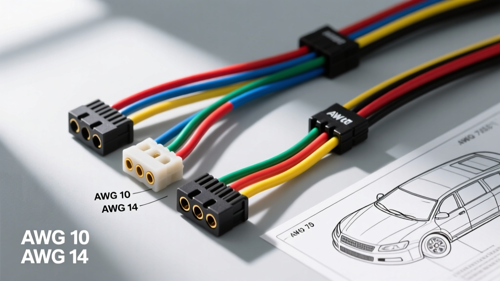
Why Upgrade From a Basic 4-Pin to a 7-Pin RV Connector?
When you purchase a used or vintage lightweight camper, it often comes equipped with a standard 4-way flat connector. While this basic setup handles stop, turn, and tail lights, it completely lacks the capacity for electric brakes, 12-volt auxiliary power, and reverse lighting. If you are planning an upgrade and modification project to make your camper highway-legal and fully functional, understanding the baseline basic camper trailer wiring diagram is your critical first step. Transitioning to a 7-way RV blade connector not only improves safety by enabling electric brake controllers but also allows your tow vehicle to maintain a charge on your camper's house battery during transit. This guide provides the exact technical specifications, wire gauges, and pinout matrices required to execute this modification flawlessly, adhering to SAE and RVIA standards.
Analyzing the Basic Camper Trailer Wiring Diagram
Before cutting into your existing harness or ordering new components, you must map the current 4-pin flat wiring. Most factory and aftermarket 4-pin harnesses follow a strict color-code standard established by the Society of Automotive Engineers (SAE). However, in older or previously modified campers, previous owners may have spliced in non-standard wires. Always verify the function of each wire using a digital multimeter set to DC voltage and continuity testing before assuming the color codes are accurate.
Standard 4-Pin Flat Connector Baseline
| Pin Position | Wire Color | Function | Minimum AWG | Max Amperage |
|---|---|---|---|---|
| 1 (Ground) | White | Chassis Ground | 16 AWG | N/A |
| 2 (Tail) | Brown | Running / Marker Lights | 18 AWG | 8A |
| 3 (Left) | Yellow | Left Turn / Stop | 16 AWG | 10A |
| 4 (Right) | Green | Right Turn / Stop | 16 AWG | 10A |
Note: If your camper utilizes incandescent bulbs rather than LEDs, the running light circuit (Brown) can easily draw 6-8 amps. When upgrading, consider switching to LED marker lights to reduce the load and minimize voltage drop across the harness.
The 7-Pin RV Blade Upgrade Modification
To support electric brakes and auxiliary power, you will be splicing into or entirely replacing the basic camper trailer wiring diagram with a heavy-duty 7-way RV blade harness. This requires routing new, thicker gauge wires from the front tongue junction box back to the axle hubs and the interior battery bank. According to the Recreational Vehicle Industry Association (RVIA), all exterior low-voltage wiring must be protected from abrasion and moisture.
Required Tools and Materials
- Wire: Automotive-grade primary wire (GXL or TXL cross-linked insulation for high heat and moisture resistance).
- Terminals: Heat-shrink ring terminals and butt connectors (nylon-insulated, 12-10 AWG).
- Protection: Split corrugated wire loom (1/4 inch and 3/8 inch), adhesive-lined marine heat shrink, and dielectric grease.
- Tools: Heavy-duty ratcheting crimp tool, wire strippers, digital multimeter, and a heat gun.
7-Way RV Blade Pinout and Color Code Matrix
The 7-way RV blade connector is the industry standard for travel trailers and campers. Below is the definitive pinout guide for your modification project. Note the increased wire gauge requirements for the brake and auxiliary circuits to prevent dangerous voltage drops.
| Pin (Clock Position) | Wire Color | Function | Required AWG | Notes / Modification Action |
|---|---|---|---|---|
| 1 (7 O'Clock) | White | System Ground | 10 AWG | Must bond directly to clean, bare camper chassis steel. |
| 2 (1 O'Clock) | Brown | Tail / Running Lights | 12 AWG | Splice into existing brown wire; upgrade if running incandescent. |
| 3 (5 O'Clock) | Green | Right Turn / Stop | 12 AWG | Splice into existing green wire. |
| 4 (11 O'Clock) | Black | 12V Auxiliary Power | 10 AWG | Route to camper battery positive via a 30A inline breaker. |
| 5 (9 O'Clock) | Blue | Electric Brakes | 10 AWG | Route to brake magnets and breakaway switch. |
| 6 (3 O'Clock) | Red / Black | Left Turn / Stop | 12 AWG | Splice into existing yellow wire (Note: RV blade uses Red for Left, but trailer side often remains Yellow). |
| 7 (Center) | Yellow / Purple | Reverse Lights / Aux | 12 AWG | Optional: Connect to reverse lockout solenoid on surge brakes. |
Reference: For comprehensive vehicle-side and trailer-side wiring FAQs, consult etrailer's wiring database to verify specific tow vehicle adapter requirements.
Integrating Electric Brakes and the Breakaway Switch
The most critical safety aspect of this upgrade is the electric brake circuit. The blue 10 AWG wire carries the modulated current from your tow vehicle's brake controller to the camper's axle magnets. Because brake magnets can draw up to 12 amps per axle (24 amps total for dual-axle campers) under heavy braking, using 12 or 14 AWG wire will result in severe voltage drop, leading to weak braking performance and overheated wires.
Breakaway Switch Wiring Logic
Federal DOT regulations require campers with electric brakes to have a breakaway switch. This device pulls a physical pin if the camper detaches from the hitch, triggering a microswitch that sends full 12V battery power directly to the brake magnets, locking the wheels to prevent a runaway trailer.
- Power Source: Wire one side of the breakaway switch directly to the positive terminal of the camper's dedicated 12V breakaway battery (or the main house battery via a 20A fuse).
- Output: Wire the other side of the switch into the blue electric brake wire after it leaves the junction box but before it splits to the left and right axle magnets.
- Isolation: Ensure the breakaway battery is wired to receive a trickle charge from the black 10 AWG auxiliary wire (Pin 4) so it remains fully charged during transit.
Professional Routing, Sealing, and Termination
A wiring diagram is only as good as its physical execution. When routing the new 10 AWG blue and black wires along the camper frame, never zip-tie wires directly to sharp steel edges or hot exhaust components. Run all wires through split corrugated loom, securing the loom to the frame with UV-resistant nylon cable ties every 12 to 18 inches. Where the harness passes through the floor or junction boxes, use rubber grommets to prevent insulation chafing.
For all terminal connections at the 7-way plug and the junction box, strip the wire precisely to the terminal's barrel length. Use a ratcheting crimp tool to ensure a gas-tight mechanical bond, then apply heat to the adhesive-lined heat shrink until the sealant oozes from the ends. Finally, pack the interior of the 7-way RV plug with a generous amount of dielectric grease (such as Permatex 22058) to displace moisture and prevent galvanic corrosion between the brass pins and copper wire.
Troubleshooting the Modified Harness
After completing the physical modification, perform a systematic diagnostic test before taking the camper on the road:
- Ground Fault Symptoms: If turn signals cause the running lights to dim or flash, you have a 'back-feed' issue caused by a high-resistance ground. Do not rely on the hitch ball for grounding. Verify the white 10 AWG ground wire has a clean, bare-metal connection to the chassis, secured with a star washer and torqued to 15-20 in-lbs.
- Voltage Drop on Aux Power: Use a multimeter to measure the voltage at the camper battery while the tow vehicle is running. If the voltage at the battery is below 13.2V while the alternator is outputting 14.2V, you are experiencing excessive voltage drop. This is usually caused by undersized wire or corroded inline fuses on the black 10 AWG auxiliary circuit.
- Brake Controller Errors: If your tow vehicle's brake controller displays an 'S.H.' (Short Circuit) or 'O.L.' (Overload) error, inspect the blue wire routing near the axle hubs. The wire may have been pinched by the suspension or rubbed bare against the leaf springs.
Authoritative References & Standards
When executing any automotive or RV electrical modification, always defer to established engineering standards. The wiring practices outlined in this basic camper trailer wiring diagram upgrade are derived from SAE J286 standards for trailer electrical connections, as well as the low-voltage wiring codes published by the RVIA. For brake controller calibration and specific pinout adapters, refer to the technical service bulletins provided by Tekonsha and Curt Manufacturing.