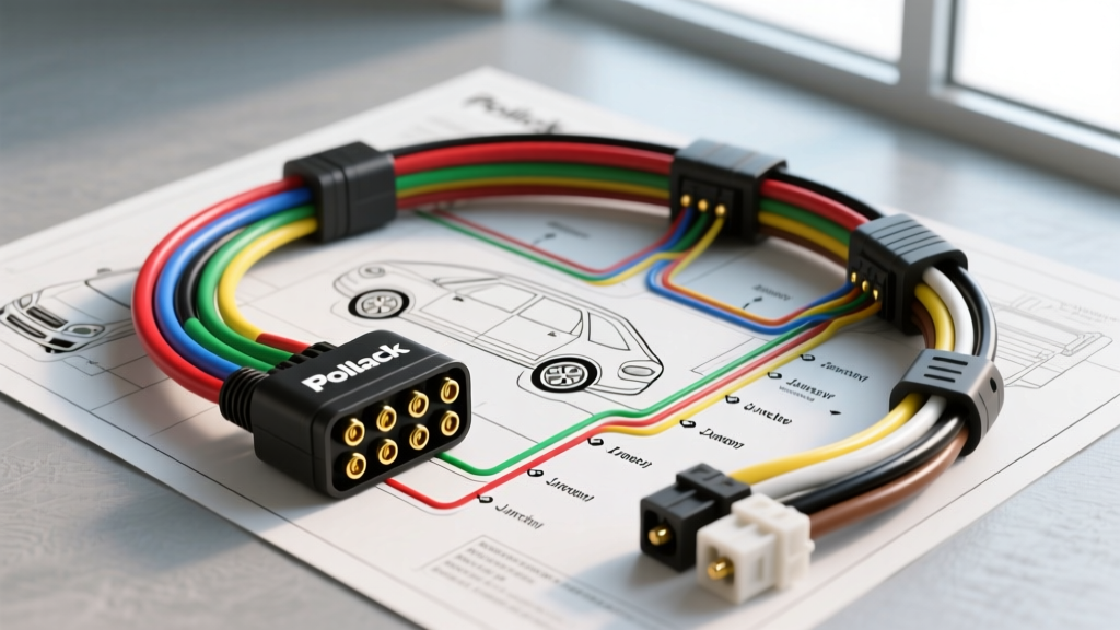
Understanding the Pollak 7-Way RV Standard (SAE J286)
When diagnosing heavy-duty towing electrical faults, referencing an accurate Pollak 7 way trailer connector wiring diagram is only the first step. The Pollak PK11898 (vehicle-side socket) and PK11720 (trailer-side plug) are the industry benchmarks for the SAE J286 RV blade standard. Unlike the USCAR standard found on modern half-ton trucks, the RV blade standard is ubiquitous on travel trailers, fifth wheels, and heavy equipment haulers. However, environmental exposure, high amperage draw from electric brakes, and improper wire gauge sizing frequently lead to cascading electrical failures. This guide provides a systematic, step-by-step troubleshooting flow designed for automotive electrical technicians and advanced DIYers to isolate voltage drops, floating grounds, and short circuits in Pollak 7-way harnesses.
Pollak 7 Way Trailer Connector Wiring Diagram & Pinout Specifications
Before connecting a multimeter, verify the harness against the SAE J286 color code and minimum AWG (American Wire Gauge) requirements. Undersized wiring is the leading cause of melted PK11720 trailer plugs and voltage drop-induced brake controller errors.
| Pin | Function | RV Standard Wire Color | Minimum AWG | Max Amperage |
|---|---|---|---|---|
| 1 | Left Turn / Stop | Yellow | 14 AWG | 10A |
| 2 | Reverse Lights | Black or Red | 14 AWG | 10A |
| 3 | Ground Return (Chassis) | White | 10 AWG (8 AWG Preferred) | 30A+ |
| 4 | Right Turn / Stop | Green | 14 AWG | 10A |
| 5 | Electric Brakes | Blue | 12 AWG (10 AWG for Dual Axle) | 20A |
| 6 | Tail / Running Lights | Brown | 14 AWG | 10A |
| 7 | 12V Auxiliary Power | Red or Black | 12 AWG | 20A |
Note: Pin 3 (White) must be bonded directly to the trailer frame with a star washer and bare metal contact. Relying on the hitch ball for a ground return will result in severe voltage drops and backfeeding.
Step-by-Step Troubleshooting Flowchart
Use the following diagnostic flow to isolate faults. You will need a digital multimeter (DMM) capable of measuring DC voltage and continuity, and a test load (such as a 21W incandescent bulb or a dedicated circuit load tester).
Phase 1: The Ground Isolation Test (Pin 3)
Approximately 80% of all trailer wiring anomalies—including hyper-flashing, cross-bleeding turn signals, and brake controller 'OL' (Open Loop) errors—stem from a compromised Pin 3 ground. Do not skip this step.
- Set DMM to DC Volts: Connect the black probe to a known good ground on the tow vehicle's chassis (not the trailer plug). Connect the red probe to Pin 3 (White wire) on the trailer side plug while the trailer is connected and running lights are ON.
- Evaluate Voltage Drop: A healthy ground circuit will read less than 0.2V. If you read 0.5V or higher, you have a high-resistance ground.
- Corrective Action: Trace the 10 AWG white wire from the PK11720 plug to the trailer frame. Remove the ring terminal, sand the frame to bare steel, apply a new crimped terminal (using a ratcheting crimper per SAE J1128 standards), and secure with a stainless steel bolt and star washer. Coat with Permatex dielectric grease to prevent galvanic corrosion.
Phase 2: Symptom-to-Pin Diagnostic Decision Tree
If the ground circuit passes Phase 1, proceed to this symptom-based decision tree to isolate the specific Pollak 7-way pin failure.
- Symptom A: Trailer Brakes Lock Up or Controller Shows 'SH' (Short)
- Step 1: Disconnect the trailer. Set DMM to Continuity/Ohms. Place one probe on the vehicle-side PK11898 Pin 5 (Blue) and the other on vehicle ground. If continuity exists, the short is in the tow vehicle's wiring harness between the brake controller and the bumper.
- Step 2: If the vehicle side is clear, test the trailer-side Pin 5 to Pin 3. A reading near 0 ohms indicates the blue brake wire is chafing against the trailer frame or the breakaway switch pin has been pulled, engaging the breakaway battery directly into the circuit.
- Symptom B: Running Lights (Pin 6) Flicker or Fail Completely
- Step 1: Check for 12V at the vehicle-side Pin 6 (Brown) with the headlights ON. If 12V is present, the fault is downstream.
- Step 2: Inspect the trailer-side junction box. The brown wire often splices into multiple marker lights. Vibration causes standard butt-splices to fail. Cut out crimp-and-tape splices and replace them with adhesive-lined heat shrink butt connectors (16-14 AWG).
- Symptom C: Turn Signals Backfeed into Running Lights (Floating Ground)
- Diagnosis: When Pin 3 fails, the 12V from the turn signal (Pin 1 or 4) seeks an alternative path to ground. It backfeeds through the dual-filament tail light bulbs into the brown running light wire, causing all marker lights to pulse in time with the turn signal.
- Fix: Re-execute Phase 1. Do not attempt to fix this by adding secondary grounds to the light fixtures; the main 10 AWG harness ground must be restored.
Phase 3: Load Testing the Electric Brake Circuit (Pin 5)
Voltage without amperage capacity is a phantom reading. A damaged 12 AWG blue wire might show 12V on a DMM, but instantly drop to 2V when the brake controller demands 15 amps to activate the trailer's electric brake magnets.
- Apply a Load: Use a dedicated 20A circuit load tester or a test light rated for trailer brakes on the trailer-side Pin 5.
- Activate Manual Override: Have an assistant slide the brake controller manual override lever to 100% output.
- Measure Voltage Under Load: If the voltage at Pin 5 drops below 10.5V under a 15A load, the 12 AWG blue wire is suffering from severe internal corrosion or strand breakage. Upgrade the entire brake circuit run from the junction box to the axles to 10 AWG stranded copper wire to minimize resistance over long trailer lengths.
Advanced Failure Modes: Terminal Tension and Corrosion
The Pollak PK11898 vehicle-side socket features a spring-loaded hinged lid to keep out moisture. However, the internal female spade terminals frequently lose their mechanical tension due to thermal cycling (heating up under heavy brake amperage and cooling down). This loss of tension creates micro-arcing, which melts the plastic housing around Pin 5 and Pin 7.
Inspection Protocol: Disconnect the battery. Use a precision terminal pick to gently bend the internal spade tabs inward, restoring the friction fit. If the plastic surrounding Pin 5 shows any brown discoloration or melting, the entire PK11898 socket must be replaced. Do not attempt to salvage a heat-damaged socket, as the increased resistance will eventually destroy your brake controller's output MOSFETs.
Furthermore, never use standard silicone grease on these connections. You must use a dedicated dielectric tune-up grease (such as Nyogel 760G or equivalent) which is formulated to displace moisture without interfering with the electrical contact points of the spade terminals.
Authoritative References
For further technical validation and OEM harness schematics, consult the following automotive electrical resources:
- Pollak Products Official Wiring Diagrams & Support - Manufacturer specifications for PK11898 and PK11720 terminal torque and insertion depths.
- etrailer.com 7-Way Trailer Wiring FAQ & SAE J286 Standards - Comprehensive database of vehicle-specific OEM tow package pinouts and adapter requirements.
- RV Industry Association (RVIA) Technical Bulletins - Industry guidelines on low-voltage DC wiring standards, AWG sizing, and overcurrent protection for recreational vehicles.