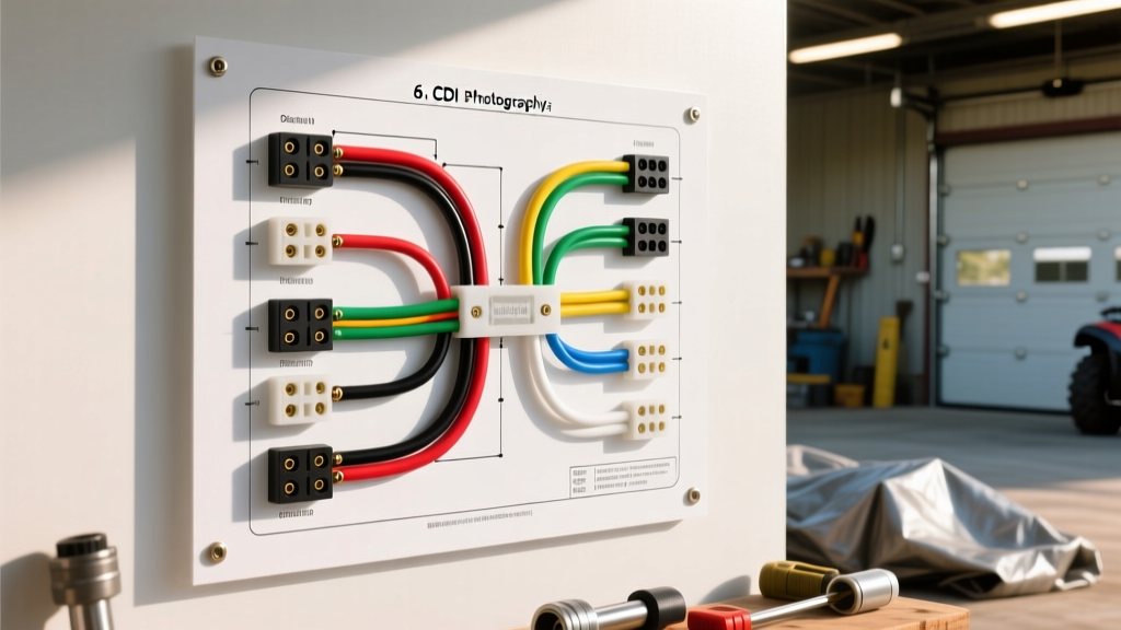
The '6 Pin CDI' Confusion: A Critical Safety Warning
Every year, our master technicians at AutoFlowWire see fried ignition modules and melted harnesses from a single, catastrophic DIY error: searching for a 6 pin CDI wiring diagram to install a trailer harness. If you own an ATV, UTV, or side-by-side (such as a Honda Rancher, Yamaha Grizzly, or Polaris Ranger), you have likely removed the side plastics and spotted a 6-pin connector near the engine block. Do not touch this connector for your trailer.
That 6-pin plug is your Capacitor Discharge Ignition (CDI) or stator harness. It carries high-voltage, unregulated 3-phase AC power (often exceeding 400V) directly from the stator to the rectifier/regulator and CDI unit. Trailer lighting requires regulated 12V DC power. Tapping into the CDI harness to power your trailer lights will instantly destroy your vehicle's ECU/CDI, blow the stator windings, and create a severe fire hazard. According to FMCSA lighting regulations and general SAE safety standards, trailer circuits must be completely isolated from the vehicle's high-voltage ignition and stator systems.
Correct 6-Pin Round Trailer Connector Pinout
Once you bypass the engine bay and locate the actual rear harness, you will need to wire a standard 6-Way Round RV-style trailer connector. This connector is ideal for mid-size UTV trailers, utility dumps, and car haulers that require electric brakes and a 12V auxiliary charge line. Below is the industry-standard pinout and wire specification chart.
| Pin / Position | Function | Wire Color | Min. AWG Size | Max Amperage |
|---|---|---|---|---|
| Pin 1 (Center) | Ground (Chassis/Battery) | White | 10 AWG | 40A |
| Pin 2 (Bottom) | Tail / Running Lights | Brown | 14 AWG | 15A |
| Pin 3 (Top Left) | Left Turn / Stop | Yellow | 14 AWG | 15A |
| Pin 4 (Top Right) | Right Turn / Stop | Green | 14 AWG | 15A |
| Pin 5 (Mid Left) | Electric Brakes | Blue | 10 AWG | 30A |
| Pin 6 (Mid Right) | 12V Auxiliary / Charge | Red or Black | 10 AWG | 40A |
Top 4 Fatal Mistakes in ATV/UTV Trailer Wiring
Mistake 1: Skipping the Taillight Converter
Most modern ATVs and UTVs utilize a 3-wire taillight system (separate circuits for running lights, brake lights, and turn signals). Standard 6-pin trailer connectors use a combined 2-wire system (brake and turn signals share the same bulb filament). If you splice the UTV's dedicated brake wire directly into the trailer's turn signal wire, you will cause backfeeding, hyper-flashing, and blown fuses. You must install a 3-to-2 wire taillight converter (such as the Curt 58240 or Tekonsha 119190) to isolate and combine the signals safely before they reach the 6-pin plug. Wire the UTV's left turn to the converter's yellow input, right turn to the green input, and brake light to the red input.
Mistake 2: Undersizing the Electric Brake Wire
Electric trailer brakes rely on electromagnetic friction. If you use standard 14 AWG or 16 AWG wire for the Blue (Electric Brake) circuit over a 15-foot trailer, you will experience severe voltage drop. A brake magnet requiring 12V might only receive 9V at the axle, reducing braking torque by up to 40%. Always use 10 AWG stranded copper wire for the blue brake circuit and the white ground circuit. For runs exceeding 25 feet, step up to 8 AWG to maintain optimal brake controller output and prevent the controller from overheating due to resistance.
Mistake 3: Relying on the Trailer Hitch Ball for Grounding
The hitch ball and coupler are made of cast steel and are constantly subjected to vibration, moisture, and road grime. Relying on the metal-to-metal contact of the hitch for your ground path is a leading cause of 'phantom' trailer light failures. The White (Pin 1) ground wire must be a dedicated 10 AWG cable ring-terminated directly to the UTV's battery negative terminal or a clean, bare-metal chassis ground bolted with a star washer. On the trailer side, the white wire must ring-terminate directly to the trailer frame, not just the coupler. Torque the ground bolt to 15 ft-lbs to ensure it bites through the paint and powder coating.
Mistake 4: Using Butt Connectors Without Heat Shrink
Trailer wiring is exposed to extreme environmental stressors: mud, water, salt, and UV radiation. Standard vinyl-crimped butt connectors will corrode within a single season, leading to high-resistance connections that melt the wire insulation. According to experts at etrailer's wiring division, all outdoor splices must utilize adhesive-lined marine-grade heat shrink terminals. The internal adhesive melts during the heating process, creating a watertight seal that prevents capillary action from drawing moisture into the copper strands.
Wire Gauge & Voltage Drop Reference Chart
When routing wires from the UTV battery, through the frame, and across the trailer tongue, distance matters. Use this chart to select the correct AWG for your 12V Auxiliary (Red) and Electric Brake (Blue) circuits based on total one-way wire length.
- Under 10 Feet: 12 AWG (Acceptable for light-duty brake setups)
- 10 to 20 Feet: 10 AWG (Standard for all electric brake and aux circuits)
- 20 to 35 Feet: 8 AWG (Required for heavy-duty car haulers and dual-axle brake setups)
- Over 35 Feet: 6 AWG (Mandatory for large RVs and gooseneck brake applications)
Troubleshooting Decision Tree: 6-Pin Connector Failures
When your trailer lighting or brake controller acts erratically, use this diagnostic sequence before replacing parts:
- Symptom: Trailer brakes lock up aggressively when UTV headlights/running lights are turned on.
Cause: Short circuit between Pin 2 (Brown/Tail) and Pin 5 (Blue/Brake) inside the molded 6-pin plug.
Fix: Inspect the pin cavities for crossed copper strands. Trim, re-strip, and ensure no bare wire bridges the gap between adjacent pins. - Symptom: UTV dashboard flickers or engine stalls when plugging in the trailer.
Cause: Severe ground fault or accidental tap into the CDI/Stator harness causing 12V DC backfeed into the AC ignition system.
Fix: Immediately disconnect. Verify you are using a dedicated taillight converter and that the 12V Aux (Red) wire is fused at 30A within 18 inches of the battery positive terminal. - Symptom: Left turn signal flashes rapidly, but trailer left light is dim or off.
Cause: High resistance on the ground path or a blown converter channel.
Fix: Test voltage between the Yellow wire and the trailer frame (not the UTV chassis). If voltage is below 11V, clean the trailer frame ground point with a wire wheel and apply dielectric grease.
Dielectric Grease and Connector Maintenance
Once your 6-pin round connector is wired and tested, the final step is environmental sealing. Apply a generous amount of silicone dielectric grease to the male and female pins of the 6-way connector before mating them. This prevents oxidation and ensures a low-resistance connection for the critical electric brake circuit. Never use petroleum-based greases like Vaseline, as they will degrade the rubber grommets and plastic housing of the connector over time. Finally, ensure all 10 AWG power and ground wires are secured with nylon loom and zip-tied away from the exhaust header and rear suspension shocks to prevent chafing and catastrophic short circuits. Never attempt to test trailer circuits using a standard 12V test light on the UTV's ECU or CDI pins; always use a high-impedance digital multimeter (DMM) to protect sensitive solid-state ignition components.