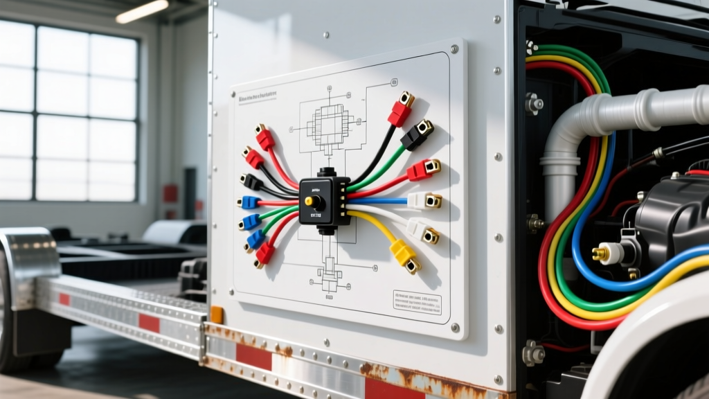
Why a 6-Pin TPS Matters for Heavy-Duty Trailer Towing
When configuring heavy-duty tow rigs for commercial flatbeds, lowboy trailers, or specialized hydraulic braking systems, standard 7-pin RV wiring is rarely sufficient. Advanced proportional trailer brake controllers, PTO-driven hydraulic winches, and auxiliary trailer retarder systems often require a real-time, analog throttle position signal from the tow vehicle to modulate trailer braking or hydraulic pump speeds. This is where the 6 pin throttle position sensor wiring diagram becomes a critical reference for automotive electricians and heavy-haul fleet technicians.
Modern Drive-by-Wire (DBW) throttle bodies and heavy-duty diesel fuel injection pumps (such as those found on Cummins ISB and Ford Powerstroke platforms) utilize a 6-pin redundant Throttle Position Sensor (TPS). Tapping into this harness to feed an aftermarket trailer controller requires a deep understanding of 5V reference circuits, signal redundancy, and Electromagnetic Interference (EMI) protection. In this cost and tool requirements analysis, we break down exactly what it takes to safely integrate a 6-pin TPS signal into a trailer towing setup without risking catastrophic PCM failure.
The 6 Pin Throttle Position Sensor Wiring Diagram & Pinout
Before purchasing diagnostic tools or wiring harnesses, technicians must understand the architecture of the 6-pin DBW TPS. Unlike older 3-pin potentiometers, the 6-pin configuration uses dual, inverse signals to allow the Powertrain Control Module (PCM) to cross-verify throttle position. If you are tapping a signal for a trailer brake controller, you must identify the correct primary signal wire and avoid loading the 5V reference circuit.
| Pin Number | Circuit Function | Typical Wire Color | Wire Gauge (AWG) | Voltage Range |
|---|---|---|---|---|
| Pin 1 | 5V Reference 1 | Red / White Stripe | 18 AWG | Steady 4.8V - 5.2V |
| Pin 2 | Signal 1 (Primary) | Green | 18 AWG | 0.5V (Idle) to 4.5V (WOT) |
| Pin 3 | Sensor Ground 1 | Black / White Stripe | 18 AWG | Less than 0.05V |
| Pin 4 | 5V Reference 2 | Purple | 18 AWG | Steady 4.8V - 5.2V |
| Pin 5 | Signal 2 (Inverse) | Yellow | 18 AWG | 4.5V (Idle) to 0.5V (WOT) |
| Pin 6 | Sensor Ground 2 | Brown | 18 AWG | Less than 0.05V |
Note: Wire colors vary by OEM and model year. Always verify with a factory service manual or Delphi Automotive Sensor Specifications before cutting or tapping.
Essential Tool Requirements for TPS Towing Integration
Integrating engine management signals with trailer wiring is not a task for a basic test light. The 5V reference circuits are highly sensitive; a short to ground or excessive current draw from a poorly designed trailer module will instantly fry the PCM's internal voltage regulator. Below is the required tooling matrix for professional-grade integration.
1. Signal Verification & Diagnostic Tools
- Automotive Oscilloscope (e.g., PicoScope 4225A): A digital multimeter (DMM) is too slow to capture voltage dropouts or EMI spikes caused by trailer brake magnets engaging. An oscilloscope allows you to map the PWM or analog sweep of Signal 1 and Signal 2 simultaneously. According to the Pico Automotive Waveform Library, verifying the inverse relationship of the dual signals is mandatory before tapping the circuit.
- High-Impedance Digital Multimeter (Fluke 87V): Required for checking ground circuit resistance. A voltage drop of more than 0.05V on the TPS ground wire will skew the signal sent to your trailer brake controller, causing erratic trailer braking.
- Back-Probe Pins & Breakout Boxes: Never pierce 18 AWG sensor wires with sharp probes, as this introduces corrosion and increases resistance. Use proper back-probing pins to test the connector from the rear.
2. Wiring & Termination Tools
- Posi-Tap Connectors (22-18 AWG): Traditional 'Scotch-Loks' or T-Taps crush the fine strands of 18 AWG wire, creating a bottleneck that causes voltage drop. Posi-Taps utilize a set-screw mechanism that maintains the structural integrity of the 5V reference and signal wires.
- Shielded Twisted-Pair Cable (20 AWG): When routing the TPS signal from the engine bay to the trailer brake controller in the cab or bed, you must use shielded cable to prevent EMI from the alternator and trailer brake power feeds.
- Deutsch DT Crimp Tool: For heavy-duty trucks utilizing Deutsch connectors at the firewall pass-through, a proper ratcheting crimp tool is required to add a secondary pigtail for the trailer module without compromising the weather seal.
Cost Breakdown: Towing Integration & Diagnostics
Understanding the financial investment required for safe integration helps fleet managers and DIY technicians budget appropriately. Cutting corners on tools or wiring materials often results in PCM replacement, which far exceeds the cost of proper diagnostic equipment.
| Item / Service | Estimated Cost | Necessity Level | Notes |
|---|---|---|---|
| PicoScope 4225A (2-Channel Kit) | $550 - $700 | Critical (Pro) | Required to verify signal integrity and EMI noise. |
| Fluke 87V Multimeter | $350 - $400 | Critical | High impedance prevents loading the 5V circuit. |
| Posi-Tap & Shielded Wire Kit | $45 - $60 | Mandatory | Prevents voltage drop and alternator whine interference. |
| OEM TPS Pigtail / Breakout Harness | $35 - $85 | Recommended | Allows plug-and-play tapping without modifying OEM harness. |
| Potential PCM Replacement (If Shorted) | $1,200 - $2,500+ | Catastrophic Risk | Cost of using cheap T-Taps or overloading the 5V Ref. |
Safe Wiring Protocol for Trailer Brake Integration
When feeding the TPS Signal 1 (Pin 2) to an external trailer module, follow this strict protocol to ensure compliance with SAE J1939 Heavy Duty Vehicle Network standards and protect the tow vehicle's CAN-bus and sensor networks.
- Isolate the Circuit: Disconnect the negative battery terminals to prevent back-feeding voltage into the PCM while working on the harness.
- Tap Signal 1 Only: Use a 22 AWG jumper wire connected via a Posi-Tap to the Primary Signal (Green wire). Never tap the 5V Reference wires to power external trailer modules; the PCM's internal 5V driver is only rated for a few milliamps and will fail if overloaded.
- Establish a Clean Ground: Do not use the TPS Sensor Ground (Pin 3 or 6) for the trailer module's ground return. This will introduce a voltage offset, causing the PCM to read an incorrect throttle position. Instead, run a dedicated 18 AWG ground wire directly from the trailer module to a clean, unpainted chassis ground or the battery negative terminal.
- Route Shielded Cable: Run the shielded signal wire through the firewall, ensuring it is routed at least 6 inches away from the trailer brake controller's 12V power feed and the alternator output cable.
- Verify with Oscilloscope: Reconnect the battery and back-probe the tapped signal. Sweep the throttle from idle to Wide Open Throttle (WOT). The voltage should sweep smoothly from 0.5V to 4.5V without any 'hash' or voltage spikes.
Diagnostic Decision Tree: Real-World Failure Modes
Integrating engine sensors with trailer wiring introduces unique failure points. Use this decision tree to diagnose issues post-installation.
- Symptom: Tow vehicle enters 'Limp Mode' and sets a P0122/P0123 code immediately after trailer brake controller is powered on.
- Cause: The trailer module is pulling excessive current from the tapped signal wire, or a T-Tap has severed the 18 AWG strand, causing an open circuit.
- Fix: Remove T-Tap, inspect wire for copper fatigue, and install an inline op-amp buffer or voltage follower circuit to isolate the PCM from the trailer module's impedance.
- Symptom: Trailer brakes pulse or apply erratically at highway speeds, even without touching the tow vehicle's brake pedal.
- Cause: Electromagnetic Interference (EMI) from the trailer's 12V brake magnets is inducing a voltage spike on the unshielded TPS signal wire. The trailer module interprets this spike as rapid throttle modulation.
- Fix: Replace the signal wire with shielded twisted-pair cable. Ground the shield drain wire at the PCM end only (to prevent ground loops).
- Symptom: Trailer braking is delayed or feels 'weak' during initial throttle tip-in.
- Cause: Voltage drop on the ground circuit. The trailer module is referencing a dirty chassis ground instead of a clean battery ground, altering the 0.5V baseline.
- Fix: Perform a voltage drop test across the module ground. Reroute ground directly to the battery.
Conclusion: Precision Over Shortcuts
Utilizing a 6 pin throttle position sensor wiring diagram for heavy-duty trailer integration is an advanced procedure that bridges the gap between powertrain diagnostics and commercial trailer wiring. By investing in proper oscilloscopes, utilizing shielded cabling, and strictly avoiding 5V reference overloads, technicians can safely harness DBW throttle data to create seamless, proportional trailer braking and hydraulic control systems. In the realm of heavy-haul towing, the cost of proper diagnostic tools is a fraction of the price of a destroyed PCM or a compromised trailer load.