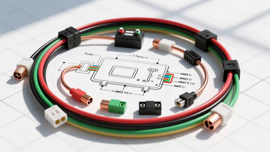
Understanding SAE J286 and the 7-Way RV Blade Architecture
When towing heavy-duty cargo, RVs, or horse trailers, the electrical demands extend far beyond basic tail lights and turn signals. The SAE J286 standard governs the 7-way RV blade connector, establishing the physical and electrical baseline for trailer wiring in North America. However, simply plugging in a harness is insufficient for modern towing. A robust 7 pin trailer wiring diagram with brakes and battery must account for Pulse Width Modulation (PWM) signals from proportional brake controllers, severe voltage drop over long trailer tongues, and the high-current demands of auxiliary battery charging.
This advanced technical guide dissects the exact wire gauge requirements, relay logic for battery isolation, and circuit protection protocols necessary for a fail-safe heavy-duty towing setup.
Complete 7 Pin Trailer Wiring Diagram with Brakes and Battery Pinout
The following table outlines the standard SAE J286 pinout for a 7-way RV connector. Note that the pin positions are described looking directly at the vehicle-side socket (female). The trailer-side plug (male) will be a mirror image.
| Pin Position | Wire Color | Function | Min. AWG (Heavy Duty) | Terminal Type |
|---|---|---|---|---|
| Pin 1 (8 o'clock) | White | System Ground | 8 AWG | Ring Terminal (Battery Neg) |
| Pin 2 (5 o'clock) | Blue | Electric Brakes Output | 10 AWG | Spade / Ring |
| Pin 3 (9 o'clock) | Brown | Tail / Running Lights | 16 AWG | Spade |
| Pin 4 (10 o'clock) | Yellow | Left Turn / Stop | 16 AWG | Spade |
| Pin 5 (2 o'clock) | Green | Right Turn / Stop | 16 AWG | Spade |
| Pin 6 (12 o'clock) | Black or Red | 12V Aux / Battery Charge | 8 AWG | Ring Terminal |
| Pin 7 (4 o'clock) | Purple | Reverse Lights / Center Aux | 16 AWG | Spade |
Electric Brake Circuit: PWM Signals and AWG Sizing
The electric brake circuit (Pin 2, Blue wire) is the most critical safety system on a multi-axle trailer. Modern proportional brake controllers, such as the Tekonsha Prodigy P3 or Redarc Tow-Pro Elite, do not send a steady 12V DC signal to the brakes. Instead, they utilize a high-frequency Pulse Width Modulation (PWM) signal to vary the magnetic field strength in the brake drums, providing smooth, proportional stopping power.
Why 10 AWG is the Absolute Minimum
A dual-axle trailer with four 10-inch or 12-inch electric brake assemblies can draw between 12 to 16 amps continuously during a maximum-effort panic stop. If you use the standard 12 AWG wire found in many pre-fabricated harnesses, the resistance over a 25-foot trailer tongue (50 feet of total round-trip wire length) will cause a significant voltage drop. According to Tekonsha's technical installation guidelines, the brake magnets must receive a minimum of 9.5 volts to generate adequate clamping force. Upgrading the blue brake wire to 10 AWG stranded copper reduces the voltage drop to less than 0.4V under a 15A load, ensuring maximum braking torque at the wheels.
Auxiliary Battery Charging: Solenoid Logic and Voltage Drop
Pin 6 (Black or Red wire) provides a 12V auxiliary feed. While often used for interior trailer lights or breakaway switch charging, its primary advanced function is maintaining the trailer's house battery or winch battery during transit. Connecting the tow vehicle’s alternator directly to the trailer battery via a standard 7-way plug is a critical error that can lead to parasitic drain, alternator overheating, and vehicle battery depletion when parked.
Continuous Duty Solenoid Integration
To safely implement the battery charging circuit, you must install a continuous duty solenoid (such as the Cole Hersee 24059 or Littelfuse 48051) under the tow vehicle's hood. This isolates the trailer battery from the vehicle's starter battery when the ignition is off.
- Terminal 30 (Input): Connect to the vehicle battery positive via a 40-amp auto-reset circuit breaker (e.g., Bussmann CB184-40) mounted within 18 inches of the battery post.
- Terminal 87 (Output): Connect to the Black/Red 8 AWG wire leading to Pin 6 on the 7-way socket.
- Terminal 85 (Coil Ground): Connect to a clean, bare-metal chassis ground.
- Terminal 86 (Coil Trigger): Connect to an ignition-switched 12V source or the alternator exciter wire. This ensures the solenoid only closes when the engine is running and the alternator is producing voltage.
Using 8 AWG wire for this circuit is highly recommended, especially for RVs with large lithium house banks or enclosed trailers with heavy-duty winches. An 8 AWG wire can safely transmit 30-40 amps over long distances while mitigating the voltage drop that would otherwise prevent the trailer battery from reaching a full absorption charge state.
The Ground Circuit: Overcoming Hitch Ball Resistance
The most common point of failure in any 7 pin trailer wiring diagram with brakes and battery is Pin 1 (White wire). Many amateur installers rely on the physical connection between the trailer coupler and the hitch ball to serve as the primary ground return path. This is a dangerous practice. Hitch balls are prone to rust, paint overspray, and grease contamination, which introduce high electrical resistance into the ground circuit.
When the ground resistance spikes, the electrical current will seek alternative paths to ground, often backfeeding through the tail light or turn signal filaments. This results in the classic 'hyper-flash' or the phenomenon where applying the brakes causes the trailer's running lights to dim or illuminate erratically.
The Expert Fix: Run a dedicated 8 AWG white ground wire from the trailer's main junction box directly to the trailer frame (using a star washer and self-tapping screw on bare metal), and ensure the vehicle-side white wire is bolted directly to the vehicle's battery negative terminal or a dedicated, heavy-duty chassis ground stud. Never rely on the hitch ball for primary ground return.
Circuit Protection and Relay Placement
Proper circuit protection is non-negotiable when dealing with high-amperage towing circuits. The wiring harness must be protected at the source, not just at the destination.
- Brake Controller Power: The heavy-gauge black wire feeding the brake controller must be protected by a 30A or 40A Maxi-fuse or auto-reset breaker within 12 to 18 inches of the vehicle battery positive terminal.
- Auxiliary 12V Feed: The wire feeding the continuous duty solenoid (Terminal 30) requires a 40A auto-reset breaker, also mounted within 18 inches of the battery.
- Lighting Circuits: The brown, yellow, green, and purple wires should be protected by a 10A or 15A mini-fuse at the vehicle's fuse box or via an inline fuse holder near the 7-way socket junction.
Always use marine-grade heat shrink butt connectors and adhesive-lined heat shrink ring terminals for all outdoor connections. Standard vinyl crimp connectors will wick moisture via capillary action, leading to copper oxidation and eventual open-circuit failures within a single season.
Advanced Troubleshooting: Voltage Drop and Ground Loops
When diagnosing faults in a 7-way system, abandon the standard 12V test light and use a digital multimeter (DMM) to perform voltage drop tests under load.
- Symptom: Brake controller displays 'S.H.' (Short Circuit) or 'O.L.' (Overload) but trailer brakes test fine on a bench.
Diagnosis: Perform a voltage drop test on the blue wire and white ground wire while a helper applies the manual override on the brake controller. A combined voltage drop exceeding 1.5V indicates undersized wiring, corroded pins in the 7-way plug, or a failing brake magnet coil. - Symptom: Trailer house battery is not charging despite 13.8V at the vehicle alternator.
Diagnosis: Measure voltage at Pin 6 on the trailer side of the plug while the engine is running. If you read 12.2V or lower, the 8 AWG charge wire is suffering from severe voltage drop, or the continuous duty solenoid contacts are pitted and introducing resistance. Clean the 7-way pins with electrical contact cleaner and apply a thin layer of dielectric grease to prevent moisture ingress. - Symptom: Trailer brakes lock up abruptly when the tow vehicle hits a bump.
Diagnosis: This is almost always a mechanical failure inside the 7-way plug where the blue wire terminal is loose and shorting against the adjacent ground or 12V pin, or the breakaway switch lanyard is snagging and pulling the pin momentarily.
Authoritative References
For further engineering specifications and compliance standards regarding heavy-duty trailer electrical systems, consult the following resources: