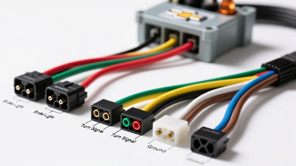
GM/Chevy Trailer Wiring Architecture Overview
Understanding the factory tow package wiring on Chevrolet Silverado and GMC Sierra trucks requires navigating GM's specific chassis harness color codes, which differ slightly from standard aftermarket trailer wiring conventions. Whether you are troubleshooting a malfunctioning 7-way RV blade, installing an aftermarket proportional brake controller, or mapping a 4-way flat connector, referencing an accurate diagram for the Chevy truck trailer wiring color code is critical. General Motors utilizes a centralized Underhood Electrical Center (UHEC) and a rear junction block to manage trailer circuits, meaning that a broken wire or missing fuse can disable specific trailer functions while leaving others intact. This technical specification reference outlines the exact pinouts, wire color mappings, and circuit protection requirements for GMT800, GMT900, and K2XX platform Chevy trucks.
Standard 7-Way RV Blade Pinout & Chevy Color Codes
The 7-way RV blade connector is the standard for heavy-duty towing, electric brakes, and auxiliary power. While the trailer-side plug follows the SAE J286 Standard for Trailer Connectors, the vehicle-side wiring harness emerging from the rear of the Chevy truck utilizes GM-specific chassis colors. Below is the definitive mapping from the GM rear tow package harness to the standard 7-way blade terminals.
| 7-Way Pin Function | SAE J286 Blade Position | GM Chassis Harness Wire Color | Circuit Protection |
|---|---|---|---|
| Left Turn / Stop Lamp | 9 o'clock (Yellow) | Yellow | 15A (Turn/Hazard) |
| Right Turn / Stop Lamp | 3 o'clock (Green) | Dark Green | 15A (Turn/Hazard) |
| Tail / Marker Lamps | 11 o'clock (Brown) | Brown | 15A (Trailer Park) |
| Ground Return | 7 o'clock (White) | White (Heavy Gauge) | N/A (Chassis Ground) |
| Electric Brake Output | 5 o'clock (Blue) | Dark Blue | 30A / 40A (Trailer Brake) |
| 12V Auxiliary Power | 1 o'clock (Black) | Red/Black or Orange | 30A / 40A J-Case Fuse |
| Backup Lamps / AUX | Center (Purple) | Light Blue or Purple | 15A (Trailer B/U) |
Note: On many GMT900 (2007-2013) and K2XX (2014+) Silverados, the 12V Auxiliary Power circuit is not active from the factory. You must install the appropriate J-Case fuse and relay in the UHEC to energize the Red/Black wire.
4-Way Flat Connector Mapping
For light-duty utility trailers without electric brakes, a 4-way flat connector is used. The GM chassis harness colors remain consistent, but the physical pin layout changes. Proper diagnosis of a 4-way flat requires testing the GM harness with a digital multimeter before assuming the trailer plug is at fault.
| 4-Way Function | Pin Shape / Position | GM Chassis Wire Color |
|---|---|---|
| Ground | Exposed Pin (White) | White |
| Tail / Running Lights | First Flat Pin (Brown) | Brown |
| Left Turn / Stop | Second Flat Pin (Yellow) | Yellow |
| Right Turn / Stop | Third Flat Pin (Green) | Dark Green |
Under-Hood Junction Block: Brake Controller Blunt-Cut Wires
One of the most unique aspects of the Chevy truck trailer wiring color code diagram is the presence of 'blunt-cut' wires tucked under the master cylinder or near the brake booster. GM provides these bare wires for the installation of aftermarket proportional brake controllers (such as the Tekonsha P3 or Redarc Tow-Pro). Instead of tapping into the stoplight switch at the pedal—which can interfere with the GM BCM (Body Control Module) and cruise control systems—installers must use these dedicated circuits.
GM Blunt-Cut Wire Identification
- Red with Black Tracer (or Solid Red): 12V Battery Feed. This wire provides heavy-duty power to the brake controller. It must be connected to the controller's black power wire and protected by a 30A or 40A inline circuit breaker.
- Dark Blue: Electric Brake Output. This wire carries the modulated voltage from the brake controller back to the trailer's 7-way plug (Pin 2). Connect this to the controller's blue output wire.
- White: Ground. Must be secured to a clean, bare metal chassis point or routed directly to the negative battery terminal. Connect to the controller's white ground wire.
- Light Blue with White Tracer: Stoplight Switch Input. This wire provides a 12V signal only when the brake pedal is depressed. Connect this to the controller's red input wire. On certain GMT800 models, this circuit requires a specific GM stoplight relay to function correctly.
For exact routing diagrams and pin locations for your specific model year, always consult the GM Upfitter Integration Guides, which provide OEM-level electrical schematics for all Silverado and Sierra platforms.
Circuit Activation: UHEC Fuses and Relays
A frequent diagnostic dead-end for Chevy truck owners is a fully wired 7-way plug that lacks 12V auxiliary power or electric brake voltage. According to etrailer's comprehensive wiring diagnostic database, this is almost always due to missing fuses and relays in the Underhood Electrical Center (UHEC). GM ships many trucks without these components installed to prevent battery drain during lot storage.
Required UHEC Components for Full 7-Way Functionality
- TRLR PWR (Trailer Power): Requires a 30A or 40A J-Case fuse (often located in slot 62 or 68, depending on the year). This activates the 1 o'clock 12V auxiliary pin.
- TRLR BRK (Trailer Brake): Requires a 30A J-Case fuse. This provides the main power feed to the under-hood blunt-cut Dark Blue brake circuit.
- TRLR B/U (Trailer Backup): Requires a 15A mini fuse and occasionally a square micro-relay to activate the center pin for reverse lights or trailer reverse lockout solenoids.
Wire Gauge (AWG) & Circuit Protection Specifications
When extending wiring, repairing chewed harnesses, or building custom pigtails, adhering to the correct American Wire Gauge (AWG) is vital to prevent voltage drop and fire hazards. Trailer lighting circuits draw minimal amperage, but electric brakes and auxiliary charging circuits require heavy-gauge copper.
| Circuit Function | Minimum AWG Required | Max Continuous Amperage | Recommended Wire Type |
|---|---|---|---|
| Ground Return (White) | 10 AWG (or 8 AWG for long rigs) | 40A+ | Stranded Copper, THHN/MTW |
| Electric Brakes (Dark Blue) | 10 AWG | 20A - 30A | Stranded Copper, SGT |
| 12V Aux / Charge Line | 10 AWG (8 AWG preferred) | 30A - 40A | Stranded Copper, SGT |
| Turn / Stop Lamps | 14 AWG (12 AWG preferred) | 10A - 15A | Stranded Copper, GXL |
| Tail / Marker Lamps | 16 AWG (14 AWG preferred) | 5A - 10A | Stranded Copper, GXL |
Diagnostic Troubleshooting for GM Tow Packages
When diagnosing trailer lighting or brake faults on a Chevy Silverado, follow this structured decision tree to isolate the failure point between the truck's BCM, the UHEC, and the physical connector.
Symptom: Trailer Brakes Do Not Engage (No Voltage at Dark Blue Pin)
- Check UHEC: Verify the TRLR BRK J-Case fuse is seated and intact.
- Test Blunt-Cut Wires: Use a multimeter to check for 12V at the under-hood Red/Black wire. If dead, trace back to the main battery junction stud.
- Verify Controller Output: Disconnect the Dark Blue wire from the brake controller. Apply manual override on the controller and test the controller's blue output wire. If the controller outputs 12V but the trailer plug has 0V, there is an open circuit in the Dark Blue wire running from the cab to the rear junction block.
Symptom: Trailer Running Lights Flicker or Fail
- Inspect the Ground: 90% of GM trailer lighting faults are caused by a corroded white ground wire at the trailer tongue or the truck's rear chassis ground stud (often located near the spare tire hoist).
- Check for BCM Protection Mode: The GM Body Control Module monitors trailer circuits for shorts. If a short occurs in the trailer's brown wire, the BCM will cut power to the trailer park lamp circuit to protect the truck. Clearing the OBD2 codes or disconnecting the truck battery for 10 minutes is often required to reset the BCM's trailer lighting driver.
- Corrosion in the 7-Way Plug: GM factory 7-way plugs are notorious for internal pin corrosion. Use dielectric grease on all terminals during reassembly to prevent moisture ingress.
By strictly adhering to this Chevy truck trailer wiring color code diagram and verifying UHEC circuit activation, you can ensure a safe, reliable, and legally compliant towing setup for any Silverado or Sierra platform.