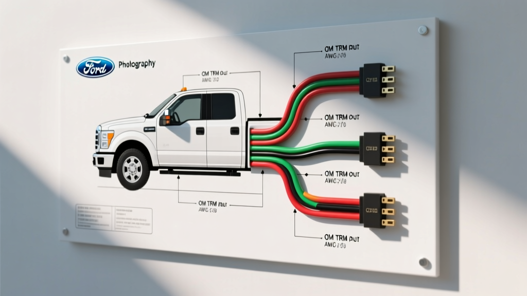
Understanding the Ford Truck Side 7-Pin Trailer Wiring Diagram
When integrating a heavy-duty trailer, fifth-wheel, or gooseneck setup with a modern Ford F-150 or Super Duty, referencing the correct Ford truck side 7-pin trailer wiring diagram is critical. Unlike older vehicles that routed analog 12V signals directly from the turn signal stalk and brake pedal switch to the rear bumper, modern Ford trucks utilize a sophisticated Trailer Relay Module (TRM) or Smart Trailer Module (STM). This module communicates with the Body Control Module (BCM) over the CAN-bus network, translating digital commands into the physical outputs required by the SAE J286 standard 7-way RV blade connector.
This technical specification reference details the exact pinout, wire gauge requirements, and module-level diagnostics for the Ford truck side 7-pin trailer wiring harness. Whether you are troubleshooting a 'Check Trailer Wiring' dash alert, installing an aftermarket proportional brake controller, or routing auxiliary power for a winch, understanding the architecture of the Ford TRM is essential for a safe and compliant upfit.
OEM Ford Truck Side 7-Pin Connector Pinout
The female 7-way receptacle mounted on the Ford bumper or truck bed adheres to the SAE International J286 and USCAR standards. The pinout below is read by looking directly at the face of the truck-side connector. The center pin is designated for reverse lockout or auxiliary functions, while the outer pins follow a specific clock-face orientation.
| Pin Number | Position (Clock Face) | Function | Standard Wire Color (Bumper Side) |
|---|---|---|---|
| Pin 1 | 7 o'clock | Ground (Chassis / Battery Return) | White |
| Pin 2 | 5 o'clock | Electric Trailer Brakes | Blue |
| Pin 3 | 11 o'clock | Tail / Running / Marker Lights | Brown |
| Pin 4 | 9 o'clock | Left Turn Signal / Stop Lamp | Yellow |
| Pin 5 | 1 o'clock | 12V Auxiliary / Battery Charge | Black (or Red) |
| Pin 6 | 3 o'clock | Right Turn Signal / Stop Lamp | Green |
| Pin 7 | Center | Backup Lights / Reverse Lockout | Purple (or Black w/ Pink Tracer) |
Wire Gauge (AWG) and Ampacity Specifications
Adhering to the correct American Wire Gauge (AWG) is vital to prevent voltage drop, especially over the 25-to-40-foot run from the Ford Battery Junction Box (BJB) or Power Distribution Box (PDB) to the rear bumper. Voltage drop on the electric brake circuit (Pin 2) can result in weak braking performance, while undersized ground wires (Pin 1) cause back-feeding and erratic trailer light behavior. The Ford Motor Company Upfitter Guidelines mandate the following minimum wire gauges for the 7-pin harness.
| Circuit Function | Minimum AWG | Max Fuse Rating (OEM) | Notes on Voltage Drop & Routing |
|---|---|---|---|
| Ground (Pin 1) | 10 AWG (or 8 AWG) | N/A | Must be bonded to a clean, bare-metal chassis point. Do not rely on the hitch ball for grounding. |
| Electric Brakes (Pin 2) | 12 AWG (10 AWG preferred) | 30A | High current draw (up to 12A per axle). 10 AWG recommended for triple-axle trailers. |
| Tail / Running (Pin 3) | 14 AWG | 15A | Susceptible to voltage drop on long trailers; ensure clean connections at the trailer junction box. |
| Left / Right Stop-Turn (Pins 4 & 6) | 14 AWG | 15A (per circuit) | TRM uses PWM for LED compatibility; standard 14 AWG is sufficient. |
| 12V Auxiliary (Pin 5) | 10 AWG | 30A or 40A Maxi | Used for charging trailer breakaway batteries or powering interior trailer lights. |
| Reverse Lockout (Pin 7) | 14 AWG | 15A | Powers the reverse lockout solenoid on surge-brake trailers to disable brakes when backing up. |
Integrated Trailer Brake Controller (ITC) & Pin 2 Architecture
In Ford trucks equipped with the factory Integrated Trailer Brake Controller (ITC), the signal sent to Pin 2 (Blue wire) is not a simple variable DC voltage. Instead, the ITC calculates the required braking force based on the vehicle's deceleration rate—measured via the yaw rate sensor and longitudinal accelerometer—and the user-defined gain and boost settings on the dash. The TRM then switches the Pin 2 circuit using a high-side MOSFET driver, outputting a Pulse Width Modulated (PWM) 12V signal.
This PWM signal ensures precise, proportional braking. If you are bypassing the Ford ITC to install an aftermarket time-delayed or proportional controller (e.g., Tekonsha P3), you must tap into the blue wire after the TRM or use the dedicated blunt-cut upfitter wires located under the driver-side dash. Tapping directly into the brake pedal switch will cause a conflict with the Ford TRM, resulting in a CAN-bus fault and disabling the trailer brake output entirely.
The 12V Auxiliary Circuit & Reverse Lockout Routing
Pin 5 (12V Auxiliary) is fed directly from the truck's BJB via a 30A or 40A Maxi-fuse, controlled by a high-amperage relay inside the TRM. In many modern F-150 and Super Duty models, this circuit is 'hot' only when the ignition is in the RUN position or the engine is cranking, preventing the trailer from draining the truck's starter battery when parked. If your trailer's breakaway battery is not charging, verify the Maxi-fuse in the under-hood PDB and check the TRM relay for internal pitting.
Pin 7 (Center Pin) is traditionally wired to the reverse lamp circuit. When the Ford transmission is shifted into Reverse, the BCM signals the TRM to energize Pin 7. This is critical for trailers equipped with hydraulic surge brakes, as it powers the reverse lockout solenoid on the trailer's master cylinder, preventing the brakes from engaging while backing into a tight campsite. According to USCAR standards, this pin should never be used for high-draw auxiliary work lights, as the TRM internal trace is typically limited to 10-15 amps.
TRM Fault Detection & 'Check Trailer Wiring' Diagnostics
One of the most common issues Ford owners face is the 'Trailer Wiring Fault' or 'Check Trailer Wiring' message on the Instrument Panel Cluster (IPC). This is a byproduct of the TRM's advanced diagnostic routines. Before applying full 12V power to the lighting circuits, the TRM sends a low-amperage micro-pulse (approximately 50mA) through Pins 3, 4, and 6 to check for circuit continuity.
If you have upgraded your trailer to LED lights without installing load resistors, the current draw will fall below the TRM's fault-detection threshold (typically 150mA). The module interprets this low draw as an 'open circuit' or blown incandescent bulb, triggering the dash alert and cutting power to the circuit. To resolve this without reverting to incandescent bulbs, you have three options:
- Install Load Resistors: Wire 50W 6-ohm resistors in parallel on the trailer's turn signal and running light circuits to simulate incandescent current draw.
- Use an LED Adapter Module: Install a Ford-approved trailer LED adapter harness (often available via the dealership parts department) which tricks the TRM into recognizing the LED signature.
- TRM As-Built Data Modification: Advanced users can use a diagnostic tool like FORScan to access the TRM's As-Built data and lower the fault-detection threshold, allowing the module to accept the low amperage of LED diodes without throwing a DTC (Diagnostic Trouble Code).
By understanding the digital handshake between the BCM, TRM, and the physical 7-pin connector, technicians and owners can accurately diagnose faults, properly size wiring for heavy loads, and ensure safe, compliant towing operations across all Ford truck platforms.