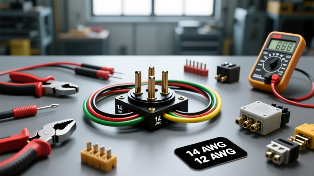
Introduction: The Ignition-Switched 7-Way Aux Circuit
When configuring a heavy-duty tow vehicle, a standard plug-and-play harness is rarely sufficient for high-draw trailer applications. The most critical modification advanced towers make involves the 12-volt auxiliary charge line. If wired directly to the battery, this circuit will drain the tow vehicle's battery when the trailer is parked and connected. To solve this, technicians utilize a 7 prong ignition switch wiring diagram to integrate a high-amperage relay, ensuring the trailer only receives charging power when the tow vehicle's engine is running.
This guide provides a comprehensive cost and tool requirements analysis for executing this specific ignition-switched relay integration. We will break down the Bill of Materials (BOM), analyze budget versus professional-grade components, and detail the exact tooling required to achieve SAE-compliant crimp terminations that survive harsh undercarriage environments.
Decoding the 7 Prong Ignition Switch Wiring Diagram
Before purchasing materials, it is vital to understand how the ignition switch interfaces with the standard SAE J286 7-way RV blade connector. The ignition switch does not power the entire trailer harness; it strictly controls the auxiliary 12V power pin to prevent parasitic battery drain while maintaining power to the trailer's breakaway system and interior lighting only during transit.
SAE J286 Standard Pinout & Ignition Integration
| Pin | Function | Standard Wire Color | AWG Size | Ignition Relay Integration? |
|---|---|---|---|---|
| 1 | Left Turn / Stop | Yellow | 12 AWG | No (Direct from BCM/Flasher) |
| 2 | Reverse Lights | Purple | 12 AWG | No (Direct from Reverse Circuit) |
| 3 | Ground | White | 8 or 10 AWG | No (Direct to Chassis/Battery) |
| 4 | Right Turn / Stop | Green | 12 AWG | No (Direct from BCM/Flasher) |
| 5 | Electric Brakes | Blue | 10 AWG | No (Direct from Brake Controller) |
| 6 | Tail / Marker Lights | Brown | 12 AWG | No (Direct from Headlight Switch) |
| 7 | 12V Auxiliary Power | Black (or Red) | 10 AWG | YES (Via 40A Ignition Relay) |
As shown in the table, Pin 7 (the 12V Aux circuit) is the sole focus of the ignition-switched modification. According to SAE International standards for trailer connectors, this circuit must be capable of handling continuous 30A to 40A loads for charging trailer house batteries or powering 12V refrigerators.
Bill of Materials (BOM) & Cost Breakdown
Executing a reliable 7 prong ignition switch wiring diagram requires marine-grade or automotive TXL (Thermoplastic Cross-Linked) wire and sealed relays. Below is a cost comparison between a budget hardware-store approach and a professional OEM-grade build.
Component Cost Analysis
| Component | Specification Requirement | Budget Cost (Est.) | Professional Cost (Est.) |
|---|---|---|---|
| Primary Power Wire | 10 AWG TXL (Black/Red) | $15 (PVC THHN) | $35 (TXL Cross-linked) |
| Circuit Breaker | 40A Auto-Reset (Type 1) | $8 | $18 (Bussmann Weatherproof) |
| Relay | ISO 5-Pin 40A (Bosch Style) | $6 (Standard) | $15 (Sealed IP67 Micro) |
| Terminals & Connectors | 10 AWG Ring/Spade, Heat Shrink | $10 (Vinyl insulated) | $25 (Adhesive-lined Delphi) |
| Ignition Trigger Wire | 14 AWG + Add-A-Fuse | $5 | $12 (Littelfuse Fused Tap) |
| 7-Way RV Socket | Pollak Heavy-Duty Die-Cast | $15 (Plastic) | $35 (Pollak Metal, Spring Lid) |
| Total Estimated BOM | $59.00 | $140.00 |
Expert Note: Never use THHN building wire for automotive trailer harnesses. THHN insulation becomes brittle at -10°C and melts under hood temperatures. Always specify SAE J1128 TXL wire, which features a thin, abrasion-resistant, high-temp cross-linked polyethylene insulation. Resources like etrailer's wiring technical guides consistently emphasize the necessity of TXL or GXL wire for undercarriage routing.
Essential Tooling for Heavy-Duty Trailer Harnesses
The most common point of failure in a custom 7-way harness is a poorly executed crimp on the 10 AWG wire. Standard pliers or cheap ratcheting crimpers will deform the terminal, leading to high resistance, voltage drop, and eventually a melted connector.
Crimping, Testing, and Sealing Requirements
- Open-Barrel Crimper (Delphi Style): Required for stamping open-barrel terminals onto 10 AWG wire. A quality tool (e.g., TE Connectivity or Titan) ensures the wire wings and insulation wings are crimped to exact factory tolerances. (Cost: $60 - $120)
- Precision Wire Strippers: Standard automatic strippers often nick 10 AWG stranded wire, reducing the cross-sectional area and creating a hot spot. Use gauge-specific manual strippers. (Cost: $25)
- Adhesive-Lined Heat Shrink (3:1 Ratio): When the heat gun is applied, the internal thermoplastic adhesive melts and seals the terminal barrel, preventing galvanic corrosion from road salt and moisture. (Cost: $20 per box)
- Digital Multimeter (DMM) with Min/Max Hold: Essential for testing voltage drop across the 40A circuit breaker and the relay contacts under load. (Cost: $50 - $150)
- Heat Gun with Reflector Nozzle: Required for evenly shrinking the adhesive heat shrink without scorching the TXL wire insulation. (Cost: $40)
Step-by-Step Ignition Relay Integration
To properly execute the 7 prong ignition switch wiring diagram, the 12V auxiliary circuit must be routed through a heavy-duty relay triggered by an ignition-hot source. Follow this exact terminal routing for a standard ISO 5-pin automotive relay:
- Pin 30 (Common / Battery Feed): Run 10 AWG Black TXL wire from the positive battery terminal to a 40A Auto-Reset Circuit Breaker, then to Relay Pin 30. Never wire the battery directly to the relay without a breaker within 18 inches of the battery post.
- Pin 87 (Normally Open / Load): Run 10 AWG Black TXL wire from Relay Pin 87 directly to Pin 7 (12V Aux) on the rear 7-way RV socket.
- Pin 86 (Coil Trigger): Run 14 AWG wire from an ignition-switched fuse in the cabin fuse box (using an Add-A-Fuse tap) to Relay Pin 86. This ensures the relay only closes when the key is in the 'ON' or 'RUN' position.
- Pin 85 (Coil Ground): Run 14 AWG wire from Relay Pin 85 to a clean, unpainted chassis ground point. Apply dielectric grease to the ground ring terminal before torquing to 10 lb-ft.
- Pin 87a (Normally Closed): This pin is left empty and insulated in this specific trailer charging application.
Common Failure Modes & Troubleshooting
Even with a perfect diagram, real-world variables can cause system faults. When troubleshooting an ignition-switched 7-way harness, technicians look for three primary failure modes:
1. Excessive Voltage Drop Under Load
If the trailer house batteries are not charging, measure the voltage at the battery post (should be ~14.2V with engine running), then measure the voltage at Pin 7 on the 7-way plug. According to Bosch automotive relay specifications, a standard ISO relay should drop no more than 0.1V to 0.2V across the contacts. If you measure a drop greater than 0.5V across the 10 AWG wire run or the relay, you have a high-resistance crimp or a corroded circuit breaker terminal.
2. Parasitic Draw via the Ignition Tap
If the tow vehicle battery dies overnight, the Add-A-Fuse tap used for Pin 86 may be inserted into a constant-hot (BAT+) circuit rather than an ignition-switched circuit. Use a DMM to verify that the trigger wire reads 0.00V when the vehicle is off and the key is removed.
3. Relay Chatter and Overheating
If the 12V trailer load exceeds 40A (e.g., running a large 12V inverter or multiple heated tank pads), the 40A relay contacts will arc, pit, and eventually weld shut. This defeats the ignition switch safety feature, leaving the circuit permanently hot. For loads exceeding 35A continuous, upgrade the diagram to use a heavy-duty solenoid (like a Trombetta or White-Rodgers continuous-duty solenoid) rated for 150A, triggered by the standard ISO relay.
Conclusion
Building a custom harness based on a 7 prong ignition switch wiring diagram is a highly effective way to protect your tow vehicle's electrical system while providing robust charging capabilities to your trailer. By investing approximately $140 in professional-grade TXL wire, sealed IP67 relays, and Bussmann breakers, and utilizing proper open-barrel crimping techniques, you will create a harness that outlasts the vehicle itself. Always verify your pinouts with a multimeter before applying full load to the trailer's battery bank.