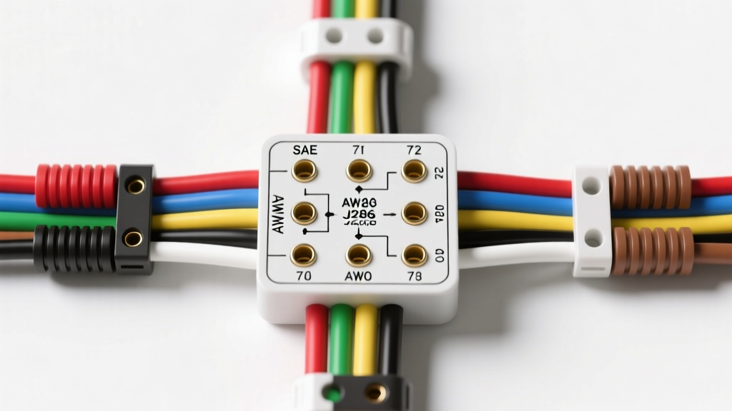
Understanding the SAE J286 7-Way RV Blade Standard
When towing travel trailers, fifth wheels, and heavy-duty utility trailers, the 7-way RV blade connector is the undisputed industry standard. Governed by the SAE J286 specification, this connector provides the necessary circuits for complex trailer operations, including electric brakes, auxiliary battery charging, and reverse lockout solenoids. Unlike the 7-way round pin connectors used in commercial and agricultural applications, the RV blade configuration utilizes flat, spade-like terminals arranged in a specific circular pattern. Miswiring this connector can lead to catastrophic brake controller failure, short circuits, or damage to the tow vehicle's Body Control Module (BCM). This technical specification reference details the exact pinout, wire color codes, American Wire Gauge (AWG) requirements, and diagnostic procedures for the 7 way RV connector wiring diagram.
7 Way RV Connector Wiring Diagram: Pinout & Color Codes
The standard SAE J286 RV blade connector relies on a strict color-coding system to maintain consistency across manufacturers like Tekonsha, CURT, and Hopkins. Below is the definitive pinout reference for the tow vehicle side (female receptacle) and the trailer side (male plug).
| Pin Position | Function | Standard Wire Color | Recommended AWG | Max Amperage |
|---|---|---|---|---|
| 8 O'Clock (Bottom Left) | Ground (Chassis) | White | 10 or 8 AWG | 40A+ |
| 10 O'Clock (Top Left) | Tail / Running Lights | Brown | 14 or 16 AWG | 10A |
| 9 O'Clock (Left) | Left Turn / Stop | Yellow | 14 or 16 AWG | 10A |
| 3 O'Clock (Right) | Right Turn / Stop | Green | 14 or 16 AWG | 10A |
| 2 O'Clock (Top Right) | Electric Brakes | Blue | 10 AWG | 30A |
| Center Pin | 12V Auxiliary Power | Black (or Red) | 10 AWG | 40A |
| 12 O'Clock (Top) | Reverse Lights / Backup | Purple | 14 AWG | 10A |
Circuit 1: Ground (White) - The Foundation of the Harness
The white ground wire is the most critical circuit in the entire 7 way RV connector wiring diagram. It completes the return path for all lighting circuits and stabilizes the reference voltage for the brake controller. A common mistake is relying on the trailer hitch ball for grounding. This is unacceptable due to paint, rust, and pivot friction. The white wire must be terminated using an 8 AWG or 10 AWG ring terminal, secured directly to the trailer's bare steel chassis using a star washer and a self-tapping bolt or welded nut. According to CURT Manufacturing Wiring Guides, over 80% of trailer lighting malfunctions, including hyper-flashing and dim running lights, stem from inadequate ground connections rather than blown bulbs or faulty sockets.
Circuit 2: Electric Brakes (Blue) & Controller Integration
The blue wire carries the modulated DC voltage from the tow vehicle's brake controller to the trailer's electric brake magnets. Because brake magnets can draw up to 6 amps per wheel (24 amps total on a quad-brake setup), a minimum of 10 AWG wire is mandatory to prevent voltage drop over the 25-to-40-foot length of the trailer. Splicing into the tow vehicle's brake light switch directly will destroy modern CAN-bus systems; instead, the blue wire must be routed through a dedicated proportional or time-delayed brake controller. For the trailer side, the blue wire splits at a junction box to feed each individual brake assembly. Ensure all brake magnet connections are sealed with adhesive-lined heat shrink to prevent moisture ingress, which causes the magnets to short out against the backing plate.
Circuits 3-5: Lighting (Brown, Yellow, Green)
The lighting circuits operate on standard 12V DC. The brown wire feeds the tail markers, license plate light, and clearance lights. Because an RV can have upwards of 20 LED clearance lights, the main brown trunk line should be 14 AWG, stepping down to 16 AWG or 18 AWG for individual pigtails. The yellow (left) and green (right) wires handle the combined stop and turn signals. If your tow vehicle utilizes separate stop and turn signals (common on European imports and some modern domestic trucks), you must install a 3-to-2 wire taillight converter before the 7-way socket to combine the signals into the standard SAE J286 format.
Circuit 6: 12V Auxiliary Power (Black) & Breakaway Logic
The center pin provides a constant 12V feed from the tow vehicle's battery. This circuit is primarily used to charge the trailer's breakaway battery and power interior 12V accessories while in transit. The black wire must be 10 AWG and protected by a 30A or 40A auto-reset circuit breaker mounted within 18 inches of the tow vehicle's positive battery terminal. This circuit also interfaces with the trailer's breakaway switch. In the event of a detachment, the breakaway lanyard pulls the pin, closing the switch and routing 12V power from the trailer's onboard battery directly to the blue electric brake circuit, locking the trailer wheels to prevent a runaway scenario. Detailed integration schematics can be found in the Tekonsha Installation Guides.
Circuit 7: Reverse Lights & Backup (Purple)
The top pin (purple wire) is activated when the tow vehicle is shifted into reverse. On travel trailers, this typically powers reverse flood lights for night-time maneuvering. On utility trailers equipped with hydraulic surge brakes, the purple wire is wired to a reverse lockout solenoid on the brake actuator. When energized, the solenoid blocks hydraulic fluid pressure, allowing the trailer to roll backward without engaging the surge brakes. Use 14 AWG wire for this circuit, as the solenoid draw is minimal but requires a solid voltage threshold to actuate the internal plunger.
Wire Routing and Environmental Protection
Executing a flawless 7 way RV connector wiring diagram requires more than just correct pinouts; it demands rigorous environmental protection. The underbelly of a trailer is subjected to high-velocity debris, road salt, and extreme thermal cycling. All main harness trunk lines must be encased in UV-resistant polyethylene split loom tubing. Avoid using standard vinyl electrical tape for terminations, as the adhesive degrades rapidly in high heat, leading to exposed copper and galvanic corrosion. Instead, utilize marine-grade adhesive-lined heat shrink tubing and crimp connectors. Apply a liberal coating of silicone-based dielectric grease to the brass pins of the 7-way plug before every towing season to prevent oxidation and ensure low-resistance continuity.
Advanced Troubleshooting: Voltage Drop & Ground Faults
When diagnosing a malfunctioning 7-way RV connector, avoid relying solely on cheap LED test lights, which draw negligible current and can illuminate even on high-resistance, corroded circuits. Instead, use a Digital Multimeter (DMM) to perform voltage drop testing under load. According to the SAE International J286 standard and general automotive electrical best practices, a healthy circuit should exhibit no more than a 0.2V drop across the ground side and 0.5V across the power side.
To test the ground circuit, set your DMM to DC Volts. Place the red probe on the trailer's battery positive terminal and the black probe on the tow vehicle's battery positive terminal while the running lights are active. If you read more than 0.5V, your white ground wire is undersized, corroded, or poorly terminated. For brake controller diagnostics, back-probe the blue wire at the 7-way socket while manually sliding the brake controller gain knob. You should see a smooth, linear voltage increase from 0V up to 12V. Any sudden drops or erratic voltage spikes indicate a frayed blue wire or a failing brake controller internal potentiometer.