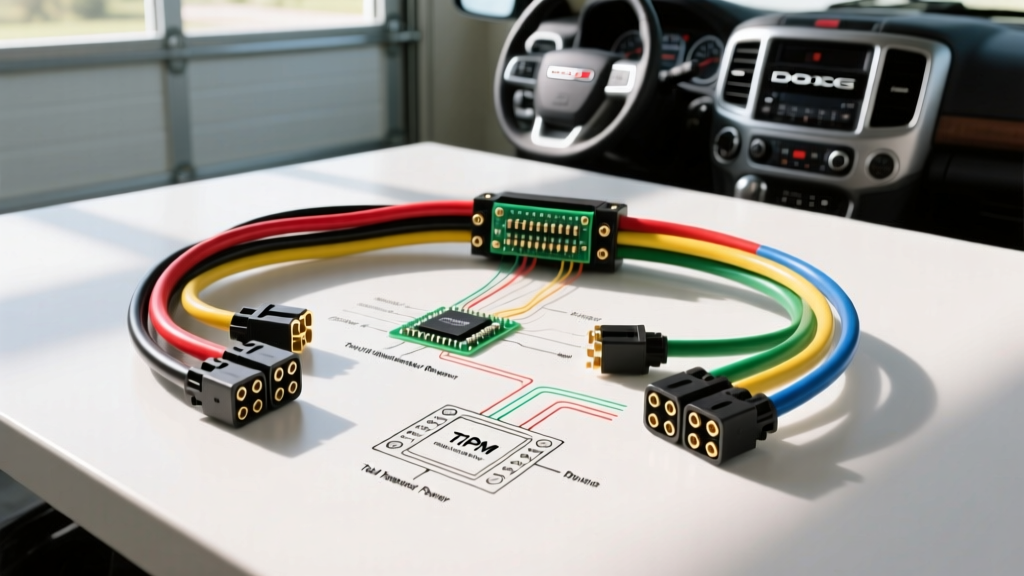
Introduction: Bridging the 7-Pin Harness and Ignition Architecture
When upgrading or troubleshooting the towing capabilities of a Dodge Ram, understanding the intersection between the trailer harness and the truck's internal power distribution is critical. Many technicians and DIYers search for a 7 pin ignition module dodge ram ignition switch wiring diagram because the trailer brake controller and the 7-pin RV blade connector rely heavily on switched 12V power derived directly from the ignition module. Whether you are working on a 3rd Generation (2002-2008) Ram with a traditional tumbler ignition switch and SKIM module, or a 4th Generation (2009-2018) Ram equipped with the Wireless Ignition Node (WIN) and Totally Integrated Power Module (TIPM), mapping the correct circuits is essential to prevent backfeed, blown fuses, or TIPM burnout.
This complete wiring walkthrough provides the exact pinouts, Mopar wire color codes, AWG specifications, and integration steps required to properly wire a 7-pin trailer connector and an electronic brake controller to your Dodge Ram's ignition and power distribution systems.
The Dodge Ram Ignition Module and TIPM Architecture
Unlike older vehicles where the ignition switch directly routed high-amperage 12V power to accessories, modern Dodge Rams utilize a multiplexed electrical architecture. The ignition switch (or WIN module) sends a low-voltage CAN-bus or logic signal to the TIPM. The TIPM then actuates internal micro-relays to supply power to the trailer lighting and brake controller circuits.
Ignition Switch Run/Start Circuits
To power the 'wake-up' wire on a trailer brake controller (typically the red wire), you must tap into a true ignition-switched 'Run/Start' circuit. Tapping into a constant 12V source will drain your battery and leave the brake controller vulnerable to parasitic draw. In the Dodge Ram TIPM, this is often found at the 'Trailer Brake' or 'Auxiliary' fuse slots, which are internally gated by the ignition module's logic signals.
Complete 7-Pin RV Blade Connector Pinout (SAE J286 Standard)
The 7-way RV blade connector is the standard for heavy-duty towing, providing dedicated circuits for electric brakes, auxiliary 12V power, and reverse lights. Below is the definitive pinout chart based on SAE J286 standards and Mopar factory wiring practices.
| Pin | Function | Standard Wire Color | Mopar/Dodge Ram Color | Recommended AWG | Fuse / Breaker |
|---|---|---|---|---|---|
| 1 | System Ground | White | White / Black | 10 AWG | N/A (Chassis Ground) |
| 2 | Electric Trailer Brakes | Blue | Dark Blue | 12 AWG | 30A (TIPM / Breaker) |
| 3 | Tail / Running Lights | Brown | Brown / White Tracer | 14 AWG | 15A (TIPM Relay) |
| 4 | 12V Aux / Battery Charge | Black | Red / Pink | 10 AWG | 40A (TIPM / Breaker) |
| 5 | Right Turn / Stop | Green | Dark Green | 14 AWG | 20A (TIPM Relay) |
| 6 | Left Turn / Stop | Yellow | Yellow / Red Tracer | 14 AWG | 20A (TIPM Relay) |
| 7 | Reverse Lights / Lockout | Purple | Violet / White Tracer | 14 AWG | 15A (TIPM) |
Step-by-Step Walkthrough: Integrating the Brake Controller & Ignition Switch
When installing an aftermarket proportional brake controller (such as a Tekonsha P3 or Redarc Tow-Pro), the wiring must interface seamlessly with the Dodge Ram's ignition module and the 7-pin connector. Here is the precise sequence for routing and terminating the wires.
1. Routing the Main Power and Ground (10 AWG)
Run a 10 AWG black wire from the brake controller's black terminal directly to the positive battery post. You must install a 30A or 40A inline circuit breaker within 6 inches of the battery terminal to protect against dead shorts. Connect the 10 AWG white wire to a clean, unpainted chassis ground near the driver's side kick panel or directly to the negative battery terminal. Do not rely on seatbelt bolts or thin sheet metal for the ground; voltage drop here will cause erratic brake pulsing.
2. Tapping the Ignition Switched Source (Red Wire)
The brake controller's red wire requires a 12V source that is only active when the ignition module is in the 'RUN' or 'START' position.
- For 3rd Gen Rams (2002-2008): Locate the ignition switch harness behind the steering column. Identify the Pink/White or Dark Blue ignition-run wire. Use a military-grade splice (solder and heat shrink) or a high-quality Posi-Tap to connect the brake controller's 14-16 AWG red wire. Do not use cheap scotch-locks, which cause corrosion and high resistance.
- For 4th Gen Rams (2009-2018): Do not tap the WIN module wires directly, as they are low-voltage data lines. Instead, locate the TIPM under the hood. Find the 'Trailer Brake' or 'Auxiliary Power' fuse slot. Use a fused add-a-circuit tap to pull a switched 12V signal directly from the TIPM's internal relay bus.
3. Connecting the Brake Output (Blue Wire)
Run the 12 AWG blue wire from the brake controller to the engine bay. On trucks with a factory towing package, this wire will plug into a blunt-cut pigtail located near the spare tire or under the driver's side wheel well. If your Ram lacks the factory tow package, you must route this 12 AWG blue wire all the way to the rear bumper and terminate it at Pin 2 of the newly installed 7-pin connector.
Upgrading a Factory 4-Pin to a 7-Pin Harness
If your Dodge Ram only has a 4-pin flat connector, you must add the missing circuits (Electric Brakes, 12V Aux, and Reverse) to complete the 7-pin diagram. Purchase a Mopar OEM 4-to-7 pin adapter harness or build a custom pigtail using a heavy-duty 7-way socket and 10/12/14 AWG cross-linked polyethylene (XLPE) automotive wire.
Critical Step: The 12V Aux circuit (Pin 4, Black wire) draws significant amperage when charging a trailer battery or powering a winch. You must run a dedicated 10 AWG wire from the TIPM's 'Aux Trailer' relay slot directly to Pin 4. If you attempt to backfeed this through the ignition switch wiring diagram, you will melt the factory harness and potentially destroy the SKIM/WIN module.
Troubleshooting Decision Tree: TIPM and Ignition Failures
The Dodge Ram TIPM is notorious for internal relay solder joint failures, particularly regarding trailer lighting. Use this diagnostic tree before replacing expensive modules:
- Symptom: Trailer running lights (Pin 3) do not work, but turn signals function.
- Cause: Internal TIPM trailer run relay failure or blown 15A J03 fuse.
- Fix: Test for 12V at the TIPM trailer light output pin. If absent, install an external bypass relay triggered by the truck's brown tail light wire.
- Symptom: Brake controller powers on, but no voltage at Pin 2 (Blue wire) when pressing the brake pedal.
- Cause: Stoplight switch misalignment or broken wire at the brake pedal bracket.
- Fix: Verify 12V at the brake controller's red/white stoplight input wire. If missing, adjust or replace the stoplight switch at the pedal arm.
- Symptom: Parasitic battery drain overnight linked to the 7-pin harness.
- Cause: Pin 4 (12V Aux) wired to a constant hot source instead of an ignition-switched relay, or corrosion bridging Pin 1 and Pin 4 inside the socket.
- Fix: Clean the 7-pin socket with electrical contact cleaner and rewire Pin 4 to a TIPM-switched auxiliary relay.
Authoritative References and Standards
Proper automotive electrical work requires adherence to established engineering standards and manufacturer-specific body builder guidelines. The wiring configurations and AWG ratings detailed in this walkthrough are derived from the following authoritative sources:
- Ram Commercial Body Builder Guides - Official Mopar wiring schematics, TIPM pinouts, and ignition module logic diagrams for commercial and heavy-duty Ram applications.
- SAE J286 Standard - The Society of Automotive Engineers' definitive specification for 7-way RV blade connector pinouts, wire color coding, and physical dimensions.
- etrailer.com Wiring FAQ and Technical Documents - Industry-standard application guides for integrating aftermarket brake controllers with OEM multiplexed TIPM systems.
Final Safety Note
Always disconnect the negative battery terminal before splicing into the ignition switch harness or TIPM. Use a digital multimeter to verify the absence of voltage and confirm that your tapped ignition source drops to 0V when the key is removed. Properly sealing all connections with adhesive-lined marine-grade heat shrink is non-negotiable to prevent the green corrosion that plagues trailer wiring systems.