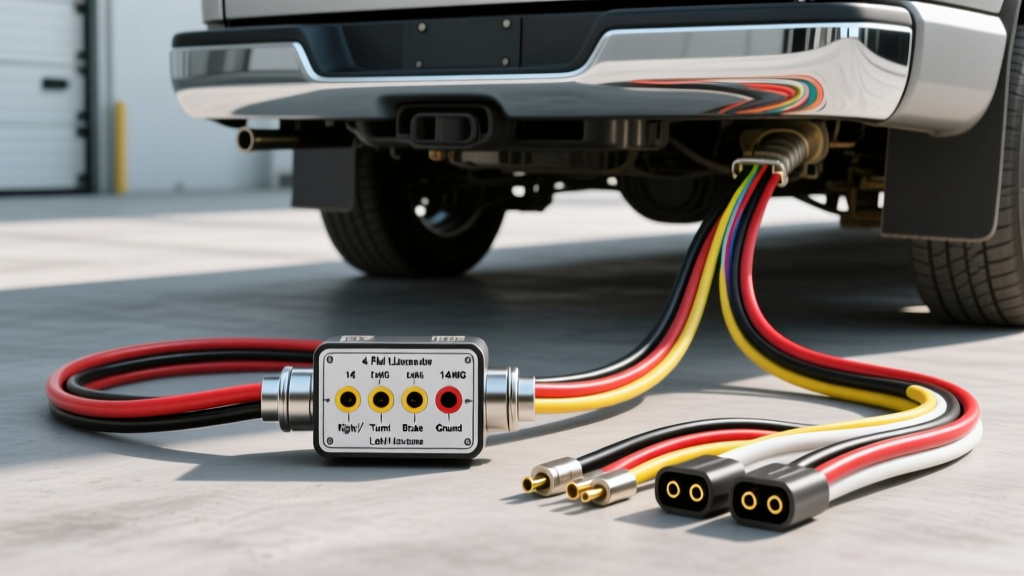
Introduction to the 4-Pin Flat Connector Standard
The 4-pin flat connector remains the undisputed industry standard for light-duty towing applications, including utility trailers, small boat trailers, jet ski rigs, and motorcycle carriers. Governed by the SAE International J286 standard, this configuration provides the essential lighting circuits required by the Department of Transportation (DOT) for trailers under 3,000 pounds GVWR. Unlike heavier 7-pin configurations that accommodate electric brakes and auxiliary 12V power, the four wire trailer wiring diagram focuses strictly on visibility: tail lights, brake lights, and turn signals. Understanding the precise pinout, wire gauge requirements, and modern vehicle integration protocols is critical for preventing electrical backfeed, blown fuses, and catastrophic Body Control Module (BCM) failures.
The Standard Four Wire Trailer Wiring Diagram
The physical design of the 4-pin flat connector is intentionally asymmetrical. The vehicle-side harness terminates in a male connector with exposed pins, while the trailer-side harness uses a female connector with shrouded receptacles. This design prevents the vehicle-side pins from shorting against the chassis or ground if the plug is dropped or drags on the pavement when disconnected. The color-coding for this system has remained standardized for decades, ensuring interoperability between manufacturers like Curt Manufacturing and Tekonsha.
Pinout Configuration and Wire Color Codes
| Pin Position | Wire Color | Circuit Function | Typical Amperage Draw (Incandescent) |
|---|---|---|---|
| Pin 1 (Leftmost) | White | Ground (Chassis Return) | N/A (Carries combined return load) |
| Pin 2 | Brown | Tail / Running / Marker Lights | 4A - 8A (depending on marker count) |
| Pin 3 | Yellow | Left Turn Signal & Brake Light | 4A - 6A |
| Pin 4 (Rightmost) | Green | Right Turn Signal & Brake Light | 4A - 6A |
Note: In North America, the brake and turn signal circuits are combined on a single wire per side (Pins 3 and 4). The vehicle's flasher relay or BCM handles the logic to pulse the brake filament when turning.
Wire Gauge (AWG) and Amperage Specifications
A common failure point in aftermarket trailer wiring is the use of undersized wire. Many off-the-shelf replacement harnesses utilize 18 AWG wire for all circuits. While 18 AWG can theoretically handle the amperage of a few incandescent bulbs, it fails to account for voltage drop over the length of the trailer. When voltage drops below 11.5V at the trailer axle, incandescent bulbs dim, and LED driver modules may flicker or fail to illuminate.
Minimum AWG Requirements by Circuit Length
| Total Harness Length (Vehicle to Trailer Axle) | Ground Wire (White) | Lighting Circuits (Brown, Yellow, Green) |
|---|---|---|
| Under 15 Feet | 16 AWG | 18 AWG |
| 15 to 25 Feet | 14 AWG | 16 AWG |
| Over 25 Feet | 12 AWG | 14 AWG |
The white ground wire must always be one gauge size thicker than the power wires. This is because the ground wire carries the combined return current of all illuminated circuits simultaneously. If the running lights, brake lights, and side markers are all active, the ground wire may carry upwards of 12-15 amps.
Modern Vehicle Integration: Powered Converters vs. Direct Splicing
When executing a four wire trailer wiring diagram installation on any vehicle manufactured after 2010, direct splicing into the vehicle's tail light wires is highly discouraged. Modern vehicles utilize multiplexed wiring, CAN-bus networks, and Pulse Width Modulation (PWM) to control exterior lighting. The BCM monitors the current draw of the lighting circuits to detect blown bulbs. Adding the inductive load of trailer lights will trigger a 'bulb out' error on the dashboard and may cause the BCM to shut down the circuit entirely to protect itself.
Step-by-Step Powered Converter (Modulite) Installation
- Locate the Signal Wires: Use a digital multimeter or logic probe to identify the vehicle's left turn, right turn, and tail light wires behind the rear tail light assemblies.
- Connect the Signal Inputs: Splice the converter's low-amperage input wires (Yellow, Green, Brown) into the vehicle's corresponding wires. These wires only draw milliamps to signal the internal relays.
- Route the Heavy-Gauge Power Wire: Run the included 12 AWG black power wire directly from the converter to the vehicle's battery positive terminal. Never route this through the ignition switch or an existing fuse panel.
- Install the Inline Fuse: Place a 20A or 30A MAXI fuse holder within 6 inches of the battery positive terminal to protect the main power feed.
- Establish the Vehicle Ground: Secure the converter's white ground wire to a clean, unpainted, bare metal surface on the vehicle's unibody or frame using a self-tapping star washer screw.
Advanced Troubleshooting: Real-World Failure Modes
Trailer lighting issues are rarely caused by a broken wire; they are almost always the result of ground degradation, corrosion, or incorrect load balancing. Use the following diagnostic matrix to isolate faults in your 4-pin flat setup.
Symptom-Cause-Fix Diagnostic Matrix
| Observed Symptom | Root Cause Analysis | Corrective Action |
|---|---|---|
| Running lights dim when brake pedal is pressed. | Poor trailer ground causing backfeed through the brake filament to the tail light circuit. | Clean trailer frame ground point; upgrade white ground wire to 12 AWG. |
| Left turn signal hyper-flashes on vehicle dash. | LED trailer lights draw insufficient current for the vehicle's thermal flasher relay or BCM logic. | Install an LED-specific smart flasher relay or add load-resistors to the trailer harness. |
| Right brake light works, but right turn signal does not. | Corrosion inside the 4-pin female connector on Pin 4 (Green), or a severed green wire at the trailer tongue hinge. | Test Pin 4 with a test light; replace female plug or repair broken wire at the hinge point. |
| Vehicle blows tail light fuse immediately upon plugging in trailer. | Dead short in the trailer's brown (running light) wire, usually where it passes through the metal tongue without a grommet. | Inspect trailer tongue routing; install rubber grommets and apply liquid electrical tape to abrasions. |
Grounding Best Practices and Corrosion Prevention
The most critical element of the four wire trailer wiring diagram is the white ground wire. A common misconception among novice towers is that the trailer will ground itself through the steel hitch ball and receiver. While this may provide a weak secondary path, it is entirely unreliable due to paint, grease, and rust on the hitch components. Relying on the hitch for grounding will result in 'bleed-over' lighting, where applying the brakes causes the running lights to illuminate faintly.
Always run a dedicated, heavy-gauge white wire from the 4-pin connector directly to the trailer frame. Use a ring terminal coated in dielectric grease, secured with a stainless steel bolt and star washer to bite through the frame's powder coating or rust. Furthermore, apply a liberal amount of silicone dielectric grease inside the 4-pin plastic housing before mating the connectors. This displaces moisture and prevents the formation of copper oxide, which acts as a semiconductor and creates localized voltage drops at the plug.