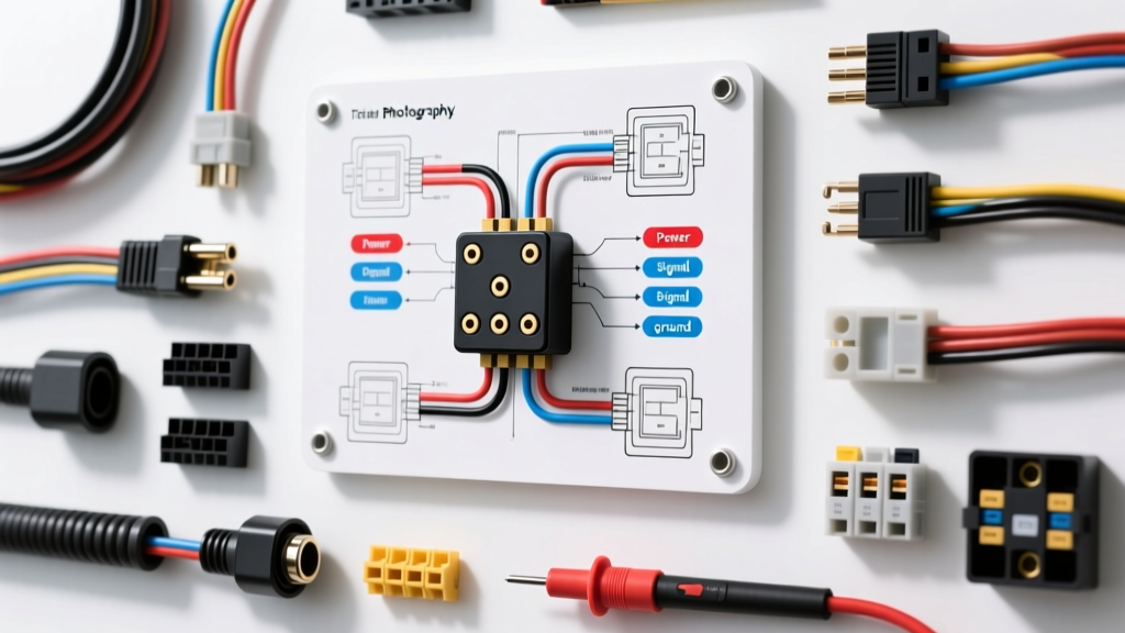
Understanding the 5-Pin ISO Relay in Trailer Harnesses
When consulting a standard 5 pins relay wiring diagram for trailer applications, you are typically looking at a Single Pole Double Throw (SPDT) ISO mini relay. Unlike the more common 4-pin SPST relay used for simple on/off switching, the 5-pin relay introduces a Normally Closed (NC) circuit. In the context of trailer wiring, this specific relay is the backbone of advanced electrical isolation. It is most frequently deployed in trailer reverse lockout circuits for surge brakes, auxiliary battery isolation to prevent the trailer from draining the tow vehicle's battery, and BCM (Body Control Module) protection to stop taillight backfeed.
Troubleshooting these circuits requires a systematic approach. A failure in the 5-pin relay network can result in trailer brakes locking up when reversing, blown tow vehicle fuses, or a dead starter battery after a weekend of camping. This guide provides an expert-level, step-by-step troubleshooting flow to diagnose and repair 5-pin relay faults in 5-way flat and 7-way RV trailer harnesses.
Standard 5 Pins Relay Wiring Diagram & Pinout Specifications
Before grabbing a multimeter, you must understand the internal topology of the SPDT relay. The standard ISO mini relay features five distinct blades. According to the Littelfuse Automotive Relay Application Guide, the pin assignments are standardized across the automotive industry, but the wire gauges and color codes must adhere to SAE J1128 and trailer-specific conventions.
| Pin Number | Function | Internal State | Recommended AWG | Typical Trailer Wire Color |
|---|---|---|---|---|
| 30 | Common (COM) | Input / Power Source | 12 AWG | Black (12V Aux) or Red (Battery) |
| 87 | Normally Open (NO) | Output (Energized) | 12 AWG | Blue (Reverse/Brake Lockout) |
| 87a | Normally Closed (NC) | Output (De-energized) | 12 AWG | Purple (Auxiliary Accessory) |
| 85 | Coil Ground | Electromagnet (-) | 16 AWG | White (Chassis Ground) |
| 86 | Coil Power | Electromagnet (+) | 16 AWG | Yellow/Red (Trigger from Reverse Light) |
Step-by-Step Troubleshooting Flow
Effective diagnostics require isolating the control circuit (the coil) from the load circuit (the contacts). Follow this sequential flow to identify the exact point of failure.
Phase 1: Verify the Trigger Circuit (Pins 85 & 86)
The most common cause of relay failure in trailer wiring is not a burnt coil, but a degraded trigger signal caused by voltage drop across corroded grounds or undersized tap wires.
- Set Multimeter to DC Volts: Connect the black probe to a known good chassis ground and the red probe to Pin 86 (Coil Power).
- Activate the Trigger: Place the tow vehicle in reverse (for lockout circuits) or turn on the running lights (for isolation circuits). You should read between 12.6V (engine off) and 14.4V (engine running).
- Test the Coil Ground (Pin 85): Move the red probe to Pin 85 and the black probe to the battery negative terminal. If you read battery voltage here while the trigger is active, your ground circuit is open or highly resistive.
- Measure Coil Resistance: With the relay removed from the harness, set the multimeter to Ohms (Ω). Probe Pins 85 and 86. A healthy 12V automotive relay coil will read between 70Ω and 90Ω. An 'OL' (Open Loop) reading indicates a snapped internal copper winding.
Phase 2: Test the Load Circuit & Contact Resistance (Pins 30, 87, 87a)
If the relay clicks audibly but the trailer accessory (e.g., reverse lockout solenoid) fails to engage, the issue lies in the high-current load circuit. Pitted contacts inside the relay can cause severe voltage drop, starving the trailer component of necessary amperage.
- Perform a Voltage Drop Test: Keep the relay plugged in and the circuit energized. Place your multimeter probes on the wires entering Pin 30 and Pin 87.
- Evaluate the Drop: As noted in etrailer.com Technical Wiring Resources, a healthy relay and connection should exhibit a voltage drop of less than 0.2V. If your multimeter reads 0.5V or higher, the internal contacts are carbon-tracked or corroded, and the relay must be replaced.
- Check the Normally Closed Circuit (87a): If using Pin 87a for a secondary function (like an auxiliary trailer light that must turn off when reversing), verify continuity between Pin 30 and Pin 87a with the relay de-energized. Loss of continuity here indicates internal mechanical spring failure.
Phase 3: Inspect the 5-Way Flat Connector & Grounds
A perfectly functioning 5-pin relay is useless if the downstream trailer connector is compromised. The 5-way flat connector utilizes a specific pinout where the 5th pin (typically Blue) carries the reverse lockout signal.
- Inspect for Galvanic Corrosion: The mating surfaces of the 5-way flat connector are highly susceptible to white, crusty aluminum oxide or green copper sulfate buildup. This acts as a resistor, dropping the 12V signal to a useless 8V before it reaches the trailer's lockout solenoid.
- Verify the Master Ground: The White wire on the trailer side must be grounded directly to the trailer frame using a star washer and self-tapping screw, sanded down to bare, shiny metal. A poor master ground will force return current to backfeed through the relay coil, causing erratic clicking and eventual coil burnout.
Real-World Failure Modes & Diagnostic Decision Tree
Use this decision tree to rapidly diagnose common symptoms associated with 5-pin relay trailer wiring configurations.
Symptom A: Trailer surge brakes lock up when reversing.
- Step 1: Check Tow Vehicle Reverse Light Bulb. (If blown, no trigger signal reaches Pin 86).
- Step 2: Probe Pin 86 on the relay harness while in reverse. (If 0V, repair the T-tap on the tow vehicle's reverse light wire).
- Step 3: If Pin 86 has 12V and relay clicks, probe the Blue wire at the 5-way flat connector. (If 0V, there is a break in the wire between Pin 87 and the connector).
- Step 4: If 12V reaches the trailer connector, the reverse lockout solenoid on the trailer brake actuator is seized or internally shorted.
Symptom B: Tow vehicle BCM blows the reverse light fuse immediately upon shifting into reverse.
- Cause: The installer wired the high-draw trailer lockout solenoid directly to the tow vehicle's reverse light wire without using the 5-pin relay as an isolator. The reverse light circuit is typically fused at 10A, while a hydraulic lockout solenoid can draw 12A-15A on startup.
- Fix: Rewire using the 5 pins relay wiring diagram. The tow vehicle reverse light wire should only trigger Pin 86 (drawing less than 0.2 Amps). Pin 30 must be wired directly to the tow vehicle's battery via a dedicated 12 AWG line with an inline 20A ATC fuse.
Best Practices for Marine and Trailer Environments
Trailer wiring exists in one of the harshest electrical environments possible: exposed to high-pressure water, road salt, and constant vibration. To ensure your 5-pin relay repair lasts, adhere to these professional installation standards:
- Never Use Vinyl Butt Connectors: Standard red/blue/yellow vinyl crimps will wick moisture via capillary action, turning the copper wire into black copper oxide within months. Use only adhesive-lined heat shrink butt connectors. The internal thermoplastic adhesive melts and seals the wire strands completely.
- Relay Orientation: When mounting the relay bracket to the chassis, orient the relay so the blade pins face downward or horizontally. Never mount a relay with the pins facing upward; if the weatherpack seal fails, gravity will pull water directly into the socket.
- Dielectric Grease Application: Apply a generous amount of silicone dielectric grease to the relay blades before inserting them into the socket. This displaces oxygen and moisture, preventing galvanic corrosion on the spade terminals. Note: Dielectric grease is non-conductive; it belongs on the outside of the mating surfaces, not bridging the gap between them.
By systematically isolating the coil trigger from the load circuit and respecting SAE wiring standards, you can permanently resolve complex trailer electrical faults and protect your tow vehicle's sensitive onboard computers.