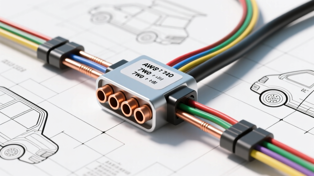
Introduction to Hydraulic Dump Trailer Electrical Systems
Wiring a hydraulic dump trailer requires a fundamentally different approach compared to standard utility or enclosed cargo trailers. While lighting and electric brake circuits remain relatively consistent across all trailer types, the hydraulic pump motor introduces a massive, intermittent DC amperage draw that standard trailer harnesses are not inherently designed to handle. A standard 7-pin RV blade connector is engineered primarily for lighting and brake controller signals, not for sustaining the 40 to 80+ amp surge required to lift a fully loaded 10,000 lb GVWR dump bed.
This technical specification reference details the proper hydraulic dump trailer wiring diagram, outlining the necessary upgrades to the standard 7-pin configuration, heavy-duty solenoid integration, and precise AWG (American Wire Gauge) sizing to prevent catastrophic voltage drop, melted connectors, and premature hydraulic pump failure. All specifications align with SAE J286 standards for trailer connectors and heavy-duty DC electrical best practices.
Standard 7-Pin RV Blade Pinout Specification
The 7-way RV blade is the industry standard for dump trailers. However, off-the-shelf harnesses typically use 14 to 16 AWG wire for lighting and 10 AWG for power/ground, which is insufficient for heavy hydraulic applications. Below is the optimized pinout configuration for a heavy-duty dump trailer.
| Pin | Function | Standard Wire Color | Standard AWG | Dump Trailer Upgraded AWG |
|---|---|---|---|---|
| 1 (Top Center) | Ground Return (White) | White | 10 AWG | 8 AWG or 6 AWG |
| 2 (Top Right) | Electric Brakes | Blue | 12 AWG | 10 AWG |
| 3 (Bottom Right) | Tail / Running Lights | Brown | 16 AWG | 14 AWG |
| 4 (Center Left) | Left Turn / Stop | Yellow | 14 AWG | 14 AWG |
| 5 (Center Right) | Right Turn / Stop | Green | 14 AWG | 14 AWG |
| 6 (Bottom Left) | 12V Auxiliary / Pump Trigger | Black or Red | 10 AWG | 10 AWG (Trigger Only) |
| 7 (Bottom Center) | Reverse Lights / Lockout | Purple | 16 AWG | 14 AWG |
The Hydraulic Pump Amperage Bottleneck
The most common failure point in a hydraulic dump trailer wiring diagram is the assumption that Pin 6 (12V Auxiliary) can directly power the hydraulic pump motor. Under no load, a standard 12V DC dump trailer pump may draw 15 to 20 amps. However, when lifting a 5-ton payload, the inrush current and sustained load amperage can easily spike to 60-90 amps.
Passing 80 amps through a standard 7-pin connector (which is typically rated for a maximum of 30-40 amps continuous per pin according to etrailer connector specifications and SAE guidelines) will result in severe resistance heating. This causes the brass pins to expand, melt the surrounding plastic housing, and create a high-resistance connection that starves the hydraulic motor of voltage. When voltage drops below 10.5V at the motor terminals, the pump slows down, draws even more amperage to compensate for the lack of wattage, and eventually burns out the motor windings.
The Solution: Heavy-Duty Solenoid Integration
To resolve this, professional dump trailer manufacturers utilize Pin 6 strictly as a low-amperage trigger signal to activate a continuous-duty solenoid mounted directly on the trailer. The main hydraulic power is then drawn from the tow vehicle’s alternator/battery via a dedicated, heavy-gauge auxiliary feed, bypassing the 7-pin connector entirely for the high-amperage circuit.
Heavy-Duty Solenoid Wiring Diagram & Configuration
For a safe, high-capacity hydraulic dump trailer wiring setup, integrate a 150A or 200A continuous-duty solenoid (such as those manufactured by Trombetta or Cole Hersee). Follow this wiring topology:
- Main Power Feed (Tow Vehicle): Run a dedicated 4 AWG or 2 AWG stranded copper wire from the tow vehicle’s positive battery terminal (or high-output alternator post). Install a 70A or 100A Type III Manual Reset Circuit Breaker within 18 inches of the battery.
- Auxiliary Connector: Route this heavy-gauge wire to a separate 50A or 175A Anderson Powerpole connector, or a dedicated heavy-duty single-pin trailer connector mounted near the standard 7-pin.
- Solenoid Input (Trailer Side): Connect the heavy-gauge feed from the Anderson plug to the primary input terminal (usually marked 'B' or 'BAT') of the continuous-duty solenoid.
- Solenoid Output to Motor: Run 4 AWG wire from the solenoid output terminal (marked 'M' or 'MTR') directly to the positive terminal of the hydraulic pump motor.
- Trigger Circuit (Pin 6): Wire the 7-pin’s Pin 6 (Black/Red, 10 AWG) to the solenoid’s ignition/trigger coil terminal (often marked 'I' or 'S'). This circuit only draws 1 to 2 amps, well within the 7-pin's safe operating limits.
- Solenoid Ground: Ground the solenoid coil's secondary terminal to the trailer chassis using a minimum 10 AWG wire and a star-washer ring terminal.
- Motor Ground: Ground the hydraulic motor's negative terminal directly to the main trailer frame using 4 AWG or 2 AWG wire. Do not rely on the motor mounting bolts for the primary ground path.
DC Voltage Drop & AWG Sizing Chart
When designing the main power feed from the tow vehicle to the trailer solenoid, you must calculate for total circuit length (Positive + Ground return). A 3% voltage drop is the maximum acceptable threshold for DC hydraulic motors to maintain optimal torque and lift speed.
| Estimated Max Load (Amps) | Total Wire Run (ft) | Recommended AWG (Copper) | Expected Voltage Drop @ 13.2V |
|---|---|---|---|
| 60A | 40 ft (20ft each way) | 6 AWG | 0.48V (3.6%) - Borderline |
| 60A | 40 ft (20ft each way) | 4 AWG | 0.30V (2.2%) - Ideal |
| 80A | 50 ft (25ft each way) | 4 AWG | 0.50V (3.8%) - Borderline |
| 80A | 50 ft (25ft each way) | 2 AWG | 0.31V (2.3%) - Ideal |
Grounding Architecture and Failure Modes
In a hydraulic dump trailer, the ground circuit is just as critical as the power circuit. The hydraulic pump motor returns massive amounts of current to the tow vehicle's battery. If the ground path has high resistance, the current will seek alternative paths, often back-feeding through the 7-pin ground wire (Pin 1), melting the connector, or frying the trailer's LED lighting modules.
Best Practices for Trailer Grounding
- Oversize Pin 1: Always upgrade the white ground wire in the 7-pin harness to match the size of the main power feed (e.g., 6 AWG or 4 AWG) if you are not using a dedicated auxiliary ground cable.
- Star Grounding: Implement a central ground bus bar or a dedicated grounding stud on the trailer tongue. Run individual ground wires from the lights, brakes, and solenoid to this central point.
- Surface Preparation: When attaching ground rings to the trailer chassis, grind away all paint, powder coating, and rust down to bare, shiny metal. Apply a conductive anti-oxidant paste (like Noalox) before torquing the bolt to 15-20 lb-ft.
- Seal Terminals: Use marine-grade heat shrink tubing with adhesive lining on all crimped connections to prevent moisture intrusion and galvanic corrosion, which drastically increases electrical resistance over time.
Diagnostic Troubleshooting Tree
When a hydraulic dump trailer fails to operate correctly, use this systematic diagnostic approach to isolate the electrical fault before replacing expensive hydraulic components.
Symptom: Solenoid Clicks Rapidly, Motor Does Not Turn
- Cause 1: Insufficient trigger voltage reaching the solenoid coil.
- Fix: Measure voltage at the solenoid trigger terminal while the remote button is pressed. If below 10.5V, inspect Pin 6 for corrosion, or upgrade the trigger wire from 12 AWG to 10 AWG.
- Cause 2: High resistance on the solenoid ground path.
- Fix: Check continuity between the solenoid casing/ground terminal and the main trailer chassis. Clean and retorque the ground connection.
Symptom: Motor Runs, But Lifts Very Slowly or Stalls Under Load
- Cause 1: Severe voltage drop on the main power or ground cables.
- Fix: Perform a live voltage drop test. Place a multimeter across the main battery positive and the motor positive while under load. A reading higher than 0.5V indicates undersized wiring or a failing breaker. Repeat for the ground side.
- Cause 2: Failing continuous-duty solenoid with internal contact pitting.
- Fix: Measure voltage across the solenoid's input and output terminals while engaged. Any voltage drop greater than 0.2V across the closed solenoid indicates internal failure; replace the solenoid.
- Cause 3: Weak tow vehicle alternator or depleted battery.
- Fix: Verify the tow vehicle is running and producing at least 13.8V to 14.4V at the battery posts. Hydraulic pumps will rapidly drain a standalone battery if the alternator is not supplying adequate amperage.
Symptom: 7-Pin Connector Gets Hot to the Touch
- Cause: The hydraulic motor is improperly wired directly through Pin 6 and Pin 1, bypassing the heavy-duty solenoid setup.
- Fix: Immediately cease operation. Rewire the system using the solenoid integration diagram outlined above. Inspect the 7-pin plug for melted housings or expanded brass pins and replace the connector if structural integrity is compromised.
By adhering to these heavy-duty wiring specifications and utilizing a solenoid-triggered architecture, you ensure that your hydraulic dump trailer operates safely, efficiently, and reliably under maximum payload conditions.