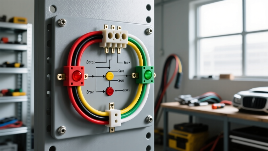
Understanding the 5-Pin Rectifier and Trailer System
When towing a trailer equipped with hydraulic surge brakes, a standard 4-pin flat connector is insufficient. You need a 5-pin flat connector to activate the reverse light circuit, which triggers the surge brake lockout solenoid. However, modern tow vehicles utilize complex multiplexed lighting, Pulse Width Modulation (PWM), and CAN-bus systems that cannot directly power trailer circuits. This is where the 5-pin rectifier—more accurately known in the automotive electrical industry as a signal isolation rectifier or powered tail light converter—becomes essential.
In trailer towing terminology, a 'rectifier' module uses internal solid-state relays and diode bridges to 'rectify' or clean up erratic vehicle signals. It isolates the trailer's electrical draw from the vehicle's sensitive Body Control Module (BCM), preventing backfeed, hyper-flashing, and BCM thermal overload. This guide provides a comprehensive, expert-level 5 pin rectifier wiring diagram and installation protocol for adapting your tow vehicle to a 5-pin flat trailer harness.
5-Pin Flat Connector Pinout and SAE Specifications
Before tapping into your vehicle's harness, you must understand the standard SAE color codes and American Wire Gauge (AWG) requirements for a 5-pin flat connector. According to SAE J1128 primary cable standards, trailer wiring must withstand harsh environmental conditions, requiring specific insulation types and gauge thicknesses to minimize voltage drop over long harness runs.
| Pin | Wire Color | Function | Min. AWG | Technical Notes |
|---|---|---|---|---|
| 1 | White | Ground (Chassis) | 12 AWG | Must ground directly to vehicle frame. Do not rely on hitch ball grounding. |
| 2 | Brown | Tail / Running Lights | 16 AWG | Handles continuous draw for all trailer marker and clearance lights. |
| 3 | Yellow | Left Turn / Stop | 16 AWG | Output from the rectifier module's left channel. |
| 4 | Green | Right Turn / Stop | 16 AWG | Output from the rectifier module's right channel. |
| 5 | Blue | Reverse / Brake Lockout | 14 AWG | Triggers the hydraulic surge brake lockout solenoid. Requires a relay. |
The 5th Pin Dilemma: Wiring the Reverse Lockout Solenoid
The most common failure point in a 5-pin trailer setup is the Blue wire (Pin 5). The reverse light circuit on a vehicle typically outputs 3 to 5 amps. However, a standard hydraulic surge brake lockout solenoid requires an 8 to 10-amp inrush current to engage the magnetic valve, dropping to a 3-amp holding current once engaged.
If you wire the vehicle's reverse light directly to the 5th pin through the rectifier module, the solenoid's inrush draw will cause a massive voltage drop. The rectifier module will overheat, or the vehicle's BCM will detect an overcurrent fault and shut down the reverse circuit entirely, leaving your trailer brakes locked in reverse.
The Solution: 12V Automotive Relay Integration
To properly wire the 5th pin, you must use the rectifier's reverse signal output to trigger a standard Bosch-style 12V 30/40A automotive relay. This allows the battery to supply the heavy inrush current directly to the solenoid, bypassing the vehicle's delicate lighting circuits.
- Pin 86 (Relay Coil +): Connect to the rectifier module's reverse output (or vehicle reverse light tap).
- Pin 85 (Relay Coil -): Connect to a clean chassis ground.
- Pin 30 (Relay Common): Connect directly to the vehicle battery positive via an inline 10A fuse.
- Pin 87 (Relay NO): Connect to the Blue wire (Pin 5) on the 5-pin flat connector.
Step-by-Step: Installing the 5-Pin Rectifier Module
For this installation, we assume you are using a powered, solid-state isolation rectifier module (e.g., Curt 56247 or equivalent), which features a dedicated 12V power feed wire. This is mandatory for modern vehicles with PWM lighting.
Step 1: Circuit Identification and Testing
Never use an incandescent test light on modern vehicle wiring; the filament draws enough current to trigger CAN-bus errors or fry a multiplexed lighting node. Use a high-impedance Digital Multimeter (DMM) or a specialized automotive logic probe. Identify the Left Turn, Right Turn, Tail Light, and Reverse Light circuits at the rear junction block or tail light harness.
Step 2: Establishing a Heavy-Duty Ground
The White ground wire is the most critical circuit in the entire 5 pin rectifier wiring diagram. Strip back the 12 AWG white wire, apply a layer of conductive anti-corrosion compound, and bolt it directly to bare, unpainted vehicle chassis metal using a self-tapping star washer. A poor ground will cause 'ground bounce,' where the trailer seeks a ground path through the turn signal circuits, resulting in erratic flashing and destroyed rectifier diodes.
Step 3: Splicing the Rectifier Inputs
Using solder-seal heat shrink butt connectors (never use cheap vinyl crimp connectors or scotch-locks, which invite moisture and galvanic corrosion), splice the rectifier's input wires into the vehicle's lighting circuits. Route the dedicated 12V power wire (usually black with an inline fuse) directly to the vehicle battery's positive terminal. This ensures the trailer's lighting draw is sourced from the battery, not the vehicle's BCM.
Step 4: Routing the Output Harness
Connect the rectifier's output wires to the corresponding 5-pin flat pigtail. Ensure the Blue wire is routed through the aforementioned 10A relay setup. Secure all wiring with split-loom tubing and UV-resistant zip ties, keeping the harness at least 6 inches away from exhaust components to prevent insulation melt-down.
Advanced Troubleshooting: Real-World Failure Modes
Even with a perfect 5 pin rectifier wiring diagram on paper, real-world installations encounter unique electrical anomalies. Here is how to diagnose the most common issues.
Symptom: Surge Brake Lockout Solenoid Chatters in Reverse
Cause: Voltage drop across the Blue wire or the White ground wire. When the solenoid attempts to pull 10 amps, the resistance in undersized wiring causes the voltage at the solenoid to drop below 10V. The solenoid disengages, the load drops, voltage recovers, and the solenoid re-engages, creating a rapid 'chatter' that will burn out the solenoid coil.
Fix: Upgrade the White ground wire to 10 AWG and ensure the Blue wire is a full 14 AWG. Verify the relay Pin 30 is pulling clean 12.6V from the battery.
Symptom: Rectifier Module Becomes Hot to the Touch
Cause: The trailer has a short circuit on the Brown (running light) or Yellow/Green (brake/turn) circuits, and you are using a non-powered (passive) rectifier module. The module is attempting to pass the full short-circuit current through its internal diodes.
Fix: Replace the passive module with a powered solid-state isolation rectifier. Powered modules use internal MOSFETs that will safely shut off the circuit if a short is detected, protecting both the module and the vehicle.
Symptom: Vehicle Dashboard Displays 'Trailer Wiring Fault'
Cause: Modern trucks (like the Ford F-150 or Ram 1500) perform a cold-check diagnostic on the trailer plug upon startup. If the rectifier module's internal impedance is too high, the BCM thinks the trailer is disconnected or has a blown bulb.
Fix: Install a CAN-bus compatible rectifier module equipped with internal load resistors, or wire external 10-ohm 50W dummy load resistors in parallel with the Left and Right turn signal outputs to simulate incandescent bulb draw. For more on OEM integration, refer to the eTrailer Comprehensive Wiring FAQ.
Final Inspection and Dielectric Protection
Once all connections are soldered, sealed with dual-wall adhesive heat shrink, and loomed, apply a liberal coating of dielectric grease to the pins of the 5-pin flat connector. This prevents copper oxidation and ensures a reliable connection every time you hook up your trailer. By treating the 5-pin rectifier not just as a simple adapter, but as a vital power distribution node, you guarantee safe, legal, and reliable towing for years to come.