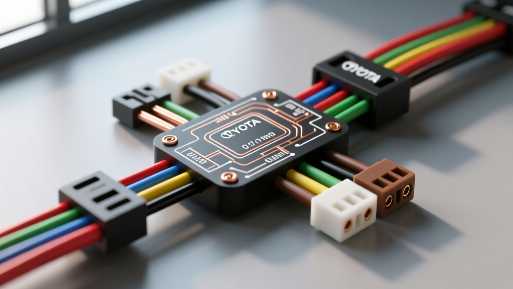
Advanced OEM Integration: Toyota Tundra 7-Pin Architecture
When configuring a heavy-duty tow rig, understanding the electrical architecture of your vehicle is paramount. The Toyota Tundra, spanning the second-generation (2007-2021) and third-generation (2022-present) platforms, utilizes a sophisticated multiplex communication network (CAN-Bus) to manage exterior lighting and trailer functions. Unlike older vehicles that routed raw 12V analog signals directly from the headlight switch to the rear bumper, the modern Tundra relies on a dedicated Tow Converter Module. This module isolates the trailer's electrical load from the Tundra's sensitive Body ECU, preventing hyper-flashing, voltage sag, and CAN-Bus fault codes.
For technicians and advanced DIYers, referencing a standard SAE J286 Standard for Trailer Connectors is only half the battle. You must also understand how the Toyota OEM harness interfaces with this standard at the rear junction block. This advanced technical deep dive will dissect the Toyota Tundra 7 pin trailer wiring diagram, detailing exact wire color codes, AWG requirements, relay logic, and ITBC (Integrated Trailer Brake Controller) protocols.
OEM 7-Pin Pinout Chart & SAE J286 Wire Color Codes
The 7-way RV blade connector on the trailer side strictly adheres to the SAE J286 standard. However, the wiring upstream of the Tundra's rear tow converter module uses Toyota-specific multiplex signals. The table below outlines the pinout at the trailer-side socket (the output of the Tundra's converter module), which is what you will be testing with a multimeter or circuit tester when diagnosing a trailer harness.
| Pin # | SAE J286 Function | Standard Trailer Wire Color | Min. AWG Req. | Circuit Protection (Tundra Fuse Box) |
|---|---|---|---|---|
| 1 | Left Turn / Stop Lamp | Yellow | 14 AWG | 15A (STOP / TURN) |
| 2 | Reverse Lamp / Aux | Black or Blue | 14 AWG | 10A (BACKUP) |
| 3 | Ground Return | White | 10 AWG | N/A (Chassis Ground) |
| 4 | Right Turn / Stop Lamp | Green | 14 AWG | 15A (STOP / TURN) |
| 5 | Electric Trailer Brakes | Blue | 10 AWG | 30A (ETCS / BRAKE CTRL) |
| 6 | 12V Aux / Battery Charge | Red or Black | 10 AWG | 30A (TOWING / CHARGE) |
| 7 | Tail / Running Lamps | Brown | 14 AWG | 15A (TAIL / TOWING) |
Factory Harness Integration & Under-Hood Relay Locations
If your Tundra did not come with the factory tow package, simply plugging in an aftermarket 4-pin to 7-pin adapter will not suffice for electric brakes or 12V auxiliary power. The factory tow package includes specific high-amperage relays located in the under-hood power distribution box. According to Toyota Technical Information System (TIS) documentation, the critical relays include the Towing Charge Relay and the Trailer Brake Relay. These are typically OEM ISO micro relays (Part # 90987-02028).
Without the factory charge relay installed, Pin 6 (12V Aux) will remain dead, meaning your trailer's breakaway battery will not charge while driving, and any powered trailer jacks will fail to operate. Furthermore, the factory tow converter module (often mounted behind the rear bumper or inside the driver-side rear quarter panel) utilizes a heavy-duty 10 AWG white ground wire. This wire must be securely bolted to the Tundra's steel frame crossmember. If this ground is compromised, the high-amperage return path from the electric brakes will backfeed through the low-amperage lighting circuits, resulting in melted 14 AWG wire insulation and blown 15A lighting fuses.
Integrated Trailer Brake Controller (ITBC) CAN-Bus Protocols
Tundras equipped with the factory ITBC do not use a simple linear voltage output for the electric brakes on Pin 5. Instead, the ITBC communicates via the vehicle's CAN-Bus network, reading the Hall-effect sensor on the brake pedal and the yaw-rate sensor to determine trailer sway. The output to the blue wire (Pin 5) is a high-frequency Pulse Width Modulated (PWM) signal.
Warning for Aftermarket Upgrades: If you are attempting to bypass the factory ITBC to install an aftermarket proportional controller (like a Tekonsha Prodigy P3), you cannot simply tap into the blue brake output wire at the 7-pin socket. The Tundra's ECU actively monitors the resistance of the blue wire circuit. Disconnecting or splicing into it without a proper CAN-Bus emulator will trigger a C1445 diagnostic trouble code (DTC) and illuminate the dashboard trailer fault warning. You must interface with the dedicated ITBC plug located under the driver-side dash, utilizing a Toyota-specific plug-and-play brake controller wiring adapter.
Heavy-Duty Upgrades: AWG Sizing & Voltage Drop Mitigation
While the SAE J286 standard and OEM pigtails often utilize 12 AWG wire for the electric brake circuit (Pin 5), this is a known failure point for heavy triple-axle trailers or equipment haulers exceeding 10,000 lbs. Over a 25-foot trailer tongue and an additional 30 feet of internal trailer wiring, 12 AWG copper wire experiences significant voltage drop. If the Tundra outputs 12.4V at the socket, the brake magnets at the rearmost axle may only see 9.5V under heavy load, resulting in asymmetric braking and premature magnet wear.
The Autoflowwire Upgrade Protocol:
- Main Brake Feed: Upgrade the continuous run from the Tundra's 7-pin socket to the trailer's main junction box using 10 AWG stranded copper wire (SAE J1128 spec).
- 12V Aux Circuit: If running a heavy-duty electric winch or hydraulic dump bed pump off the Tundra's Pin 6, bypass the factory 30A fuse limitation. Run a dedicated 8 AWG wire directly from the Tundra's alternator stud, protected by a 50A marine-grade auto-reset circuit breaker mounted within 18 inches of the battery positive terminal.
- Connector Terminals: Never use solder on the 7-way blade connector pins. Solder becomes brittle under the high-vibration environment of a trailer hitch and will crack, leading to high-resistance arcing. Use a ratcheting closed-barrel crimper and adhesive-lined heat shrink tubing rated for 125°C.
Advanced Troubleshooting: PWM Signal Errors & LED Hyper-Flashing
A highly specific issue encountered on 2014-2021 Toyota Tundras involves the integration of LED trailer lighting. The Tundra's Body ECU performs a cold-check and warm-check on the lighting circuits by sending a brief PWM pulse to measure circuit resistance. Traditional incandescent bulbs draw high inrush current, which the ECU recognizes as a healthy circuit. Modern LED trailer lights draw less than 0.5 amps. The Tundra's ECU interprets this low draw as a 'burnt bulb' and will either cut power entirely to the running lights (Pin 7) or cause the turn signals (Pins 1 & 4) to hyper-flash.
The Engineering Solution: Do not rely on cheap inline load resistors that generate excessive heat and can melt plastic wire looms. Instead, install a Toyota-approved LED-compatible tow converter module, or wire heavy-duty 50W 6-ohm ceramic load resistors in parallel on the yellow and green turn signal circuits before they reach the trailer plug. Ensure the resistors are bolted to a metal heat sink or the steel trailer tongue, as they will reach temperatures exceeding 150°F during sustained hazard light use.
Grounding Best Practices & Galvanic Corrosion
The white ground wire (Pin 3) is the most critical circuit in the entire 7-pin diagram. The Tundra's frame is primarily high-strength steel, but many aftermarket trailer hitches and trailer tongues utilize aluminum or galvanized steel. When copper wire terminals contact dissimilar metals in the presence of road salt and moisture, galvanic corrosion occurs rapidly, creating a high-resistance diode effect.
To prevent ground-return failure modes:
- Strip the paint and powder coating down to bare, shiny metal using a 3M Roloc disc.
- Apply a liberal coat of No-Ox-Id A-Special conductive grease to the terminal and bare metal surface. This prevents oxygen and moisture from reaching the copper.
- Use a stainless steel star washer to bite into the metal, followed by a Grade 8 hex bolt.
- Torque the ground bolt to exactly 12 ft-lbs. Over-torquing can strip the threads in thin-walled square-tube bumper hitches, while under-torquing allows micro-movements that lead to fretting corrosion.
Authoritative References
For further engineering schematics and OEM service manuals, technicians should consult the following resources: