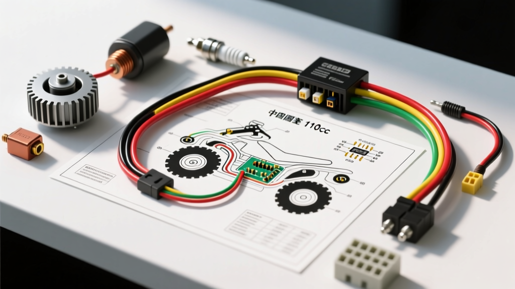
Why Factory 110cc Chinese ATV Wiring Fails
Owning a 110cc youth or utility quad from manufacturers like TaoTao, Apollo, Roketa, or Kazuma is an exercise in mechanical self-reliance. While the horizontal single-cylinder engines are virtually bulletproof, the electrical harnesses are notoriously fragile. Factory wiring often utilizes undersized 20 AWG copper-clad aluminum (CCA) wire, brittle PVC insulation that cracks under UV exposure, and unsealed spade connectors that corrode within weeks of riding in damp conditions.
Before embarking on any modification project, you must understand the baseline chinese atv wiring diagram 110cc architecture. Most 110cc quads utilize a magneto-style AC ignition system paired with a dual-purpose stator that handles both ignition sourcing and raw AC lighting power. This guide will walk you through decoding the factory schematic and executing three critical upgrades: converting to DC lighting, installing a high-output stator, and rebuilding the ground network.
Decoding the Baseline: Stator and CDI Pinouts
The heart of the 110cc electrical system is the 5-wire stator and the 5-pin AC CDI (Capacitor Discharge Ignition). Unlike DC-CDI systems found on larger Japanese machines, the AC-CDI relies on a dedicated high-voltage source coil on the stator to charge its internal capacitor, completely independent of the 12V battery. This means your 110cc ATV will generate spark even with a completely dead or disconnected battery.
5-Wire Stator Color Code Matrix
| Wire Color | Function | Destination | Typical AC Voltage |
|---|---|---|---|
| Black/Red | Source Coil (High Voltage) | CDI Pin 1 | 100V - 400V AC |
| Blue/White | Pulse / Trigger Coil | CDI Pin 3 | 0.5V - 2.0V AC |
| Yellow | Lighting Coil (Main AC) | Regulator / Headlight | 12V - 35V AC (RPM dependent) |
| White / Pink | Secondary AC / Ignition Kill | Regulator / CDI | 12V - 20V AC |
| Green | Stator Ground | Chassis / CDI Pin 4 | N/A |
5-Pin AC CDI Configuration
When tracing your chinese atv wiring diagram 110cc, the CDI connector is the most common point of diagnostic confusion. The standard 5-pin layout is as follows:
- Pin 1 (Black/Red): DC input from the Stator Source Coil. This provides the raw energy for the spark.
- Pin 2 (White or Black/White): Kill Switch circuit. When grounded, it shorts the CDI and stops the engine.
- Pin 3 (Blue/White): Trigger signal from the pulse coil. Tells the CDI exactly when to fire.
- Pin 4 (Green): Main CDI Ground. Must have absolute continuity to the engine block.
- Pin 5 (Black/Yellow): High-voltage output to the primary side of the ignition coil.
Upgrade Project 1: The AC to DC Lighting Conversion
The most dangerous flaw in the factory 110cc wiring diagram is the AC headlight circuit. From the factory, the headlight is wired directly to the Yellow stator wire. The regulator/rectifier attempts to clip the voltage, but if the headlight bulb burns out while riding, the electrical load drops to zero. According to AutoShop101 Electrical Fundamentals, a sudden loss of load on an unregulated magneto coil causes a massive voltage spike. This spike frequently melts the headlight switch, fries the speedometer, or ignites the wiring harness.
The Fix: Rewire the headlight and all accessories to run on regulated 12V DC from the battery, bypassing the stator's raw AC lighting coil entirely.
- Isolate the Yellow Wire: Disconnect the Yellow wire from the headlight switch and the handlebar harness. Cap it off; you will no longer use it for lighting.
- Install a 30A Automotive Relay: Mount a standard 12V 4-pin relay near the battery. Connect Pin 86 to the ignition-switched 12V source (Red wire from the key switch). Connect Pin 85 to a clean chassis ground.
- Power the Accessories: Run a new 14 AWG wire from the battery positive terminal (fused at 15A) to Relay Pin 30. Connect Relay Pin 87 to your headlight and LED light bar positive wires.
- Ground the Lights: Do not rely on the factory light pods for grounding. Run dedicated 16 AWG ground wires from the light housings directly back to the battery negative terminal.
Upgrade Project 2: The Big Three Ground Rebuild
Chinese 110cc ATVs utilize the engine block and frame as the primary return path to the battery. However, the factory uses thin 18 AWG ground straps, and the engine mounts are often painted or powder-coated, creating high-resistance bottlenecks. Following SAE International J1128 standards for low-tension primary cable, any ground carrying starter motor or main alternator return current must be appropriately gauged to prevent voltage drop.
To eliminate dimming lights and erratic CDI misfires, perform the "Big Three" ground upgrade:
- Battery Negative to Engine Block: Upgrade to 10 AWG stranded copper wire. Crimp a heavy-duty ring terminal and bolt it directly to an unpainted engine mounting stud. Torque to 15 Nm.
- Engine Block to Frame: Run a 10 AWG braided ground strap from the cylinder head bolt to the main frame gusset. Sand the frame down to bare metal and apply dielectric grease to prevent corrosion.
- CDI Dedicated Ground: Splice a new 14 AWG wire directly into the CDI's Green ground wire (Pin 4) and route it straight to the battery negative. This ensures the CDI's microsecond trigger signals are never corrupted by frame noise.
Modification Phase 3: Connector and Harness Sealing
The final phase of your upgrade project involves replacing the factory spade terminals and cheap plastic bullet connectors. Moisture ingress is the primary killer of 110cc ATV electrical systems. When referencing broader automotive electrical best practices outlined by MotorEra Automotive Electrical Basics, sealed connections are non-negotiable for off-road vehicles.
Cut off all factory connectors at the stator, CDI, and rectifier. Replace them with Sumitomo HM 090 or Deutsch DT series sealed connectors. Use adhesive-lined marine-grade heat shrink over every crimp. For the stator exit grommet, apply a bead of RTV silicone to prevent water from wicking up inside the wire insulation via capillary action—a common failure mode that shorts the stator internally.
Wire Gauge and Component Specification Chart
| Circuit | Factory AWG (Typical) | Upgrade AWG | Connector Type | Fuse Rating |
|---|---|---|---|---|
| Main Battery Positive | 14 AWG (CCA) | 10 AWG Copper | Heavy Duty Ring | 30A Main |
| Stator to Rectifier | 18 AWG | 16 AWG Copper | Sumitomo HM 090 | N/A |
| CDI Trigger (Blue/White) | 20 AWG | 18 AWG Copper | Sealed Splice | N/A |
| Headlight Power (DC Mod) | N/A (AC wired) | 14 AWG Copper | Deutsch DT 2-Pin | 10A Inline |
| Ignition Coil Feed | 18 AWG | 16 AWG Copper | Waterproof Boot | N/A |
Troubleshooting the Upgrade
If your 110cc ATV fails to start after performing the CDI and ground upgrades, follow this decision tree:
- No Spark: Disconnect the White kill-switch wire at the CDI. If spark returns, your handlebar kill switch or ignition key cylinder is internally shorted to ground.
- Backfiring / Erratic Timing: Check the Blue/White trigger wire. If you routed it too close to the Black/Red high-voltage source coil or the ignition coil wire, electromagnetic interference (EMI) is causing false triggers. Reroute the trigger wire with at least a 2-inch separation from high-voltage lines.
- Battery Overcharging (15V+): Verify the Green ground wire on the Regulator/Rectifier. If the rectifier lacks a solid ground, it cannot properly shunt excess AC voltage, leading to boiled batteries.
By completely overhauling the harness using the correct chinese atv wiring diagram 110cc principles, you transform a liability into a reliable, high-output electrical system capable of supporting modern LED lighting, winches, and digital gauges.