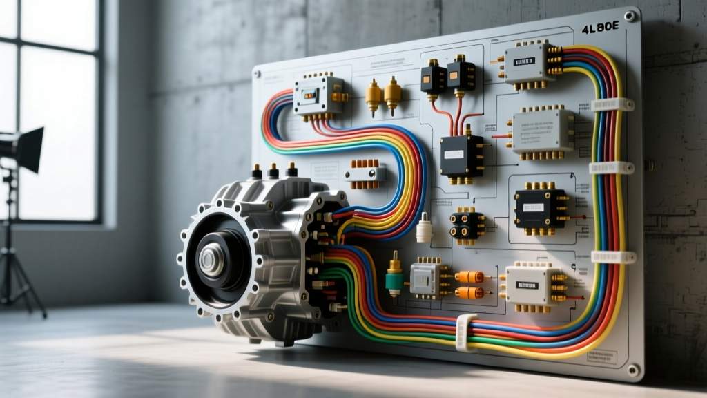
Understanding the 4L80E Electronic Control System
The GM 4L80E is a legendary heavy-duty, electronically controlled four-speed overdrive transmission derived from the robust Turbo-Hydramatic 400. However, unlike its purely hydraulic predecessor, the 4L80E relies entirely on the Powertrain Control Module (PCM) to manage shift points, line pressure, and torque converter clutch (TCC) lockup. It achieves this through a complex network of solenoids, thermistors, and variable reluctance sensors. When diagnosing shift anomalies, a generic OBD-II scan tool is rarely sufficient. You need the precise 4L80E transmission wiring diagram and a systematic troubleshooting flow to isolate whether the fault lies in the PCM, the external chassis harness, the internal transmission harness, or the component itself.
This guide provides a step-by-step diagnostic decision tree for the most common 4L80E electrical failures, focusing on the widely used 1997-2013 12-pin case connector configuration. We will cover specific wire colors, AWG ratings, resistance values, and real-world failure modes that plague these units in high-mileage and high-torque applications.
1997-2013 4L80E 12-Pin Case Connector Pinout
Before diving into the diagnostic flows, it is critical to understand the anatomy of the main case connector. The 1997 and newer 4L80E utilizes a 12-pin pass-through connector (pins A through M, skipping I). The external chassis harness plugs into the exterior, while the internal transmission harness routes to the respective components. Below is the standard pinout reference for typical GM C/K and Silverado truck applications.
| Pin | Function | Typical Wire Color (GM Truck) | AWG | Specification / Resistance |
|---|---|---|---|---|
| A | TCC PWM Solenoid | Light Green | 18 | 10-15 Ω @ 68°F |
| B | Shift Solenoid A (SSA) | Yellow | 18 | 19-24 Ω @ 68°F |
| C | Shift Solenoid B (SSB) | Dark Green | 18 | 19-24 Ω @ 68°F |
| D | TFT Sensor Signal | Light Blue | 20 | Thermistor (See Curve) |
| E | TFT Sensor Ground | Black/White | 20 | Continuity to PCM Ground |
| F | Pressure Control (PCS) High | Light Blue/Black | 18 | 3-5 Ω (Low Impedance) |
| G | Pressure Control (PCS) Low | Brown/White | 18 | Continuity to PCM |
| H | Output Speed Sensor (OSS) High | Purple | 20 | 1400-2400 Ω (AC Output) |
| J | Output Speed Sensor (OSS) Low | Light Green/White | 20 | Continuity to PCM |
| K | Input Speed Sensor (ISS) High | Yellow/Black | 20 | 1400-2400 Ω (AC Output) |
| L | Input Speed Sensor (ISS) Low | Dark Green/White | 20 | Continuity to PCM |
| M | TCC On/Off Solenoid | Tan/Black | 18 | 10-15 Ω @ 68°F |
Note: Wire colors can vary significantly between GM F-Body (Camaro/Firebird), P30 Motorhome, and C/K Truck platforms. Always verify against the factory service manual for your specific chassis.
Diagnostic Flow 1: Limp Mode (Default to 3rd Gear)
When the PCM detects a critical electrical fault, it triggers 'Limp Mode' to protect the transmission. The 4L80E defaults to 3rd gear, line pressure maximizes (resulting in harsh engagements), and the TCC is disabled. This is most commonly caused by an open or shorted Shift Solenoid A (SSA) or Shift Solenoid B (SSB).
Step-by-Step Troubleshooting:
- Scan for DTCs: Look for P0740, P0751, P0753, P0756, or P0758. Note whether the code indicates a 'circuit open' or 'circuit shorted to ground'.
- External Harness Test: Disconnect the main 12-pin case connector. Using a Digital Multimeter (DMM) set to Ohms, probe the chassis side of the harness. Measure from the solenoid feed wire (e.g., Pin B for SSA) to a known good ground. If you read infinite resistance (OL), the break is in the chassis harness or the PCM driver.
- Internal Component Test: Probe the transmission side of the case connector. Measure Pin B to Pin E (Ground). You should read 19 to 24 ohms at room temperature (68°F).
- If reading is OL (Open): The internal harness is broken, or the solenoid coil is burnt out.
- If reading is near 0 Ω (Short): The solenoid coil has shorted internally, or the internal wiring insulation has melted and crossed circuits.
- PCM Verification: If both harness and component test perfectly, use a test light or logic probe on the PCM connector (typically C1 or C2 depending on the year) while the engine is running to verify the PCM is providing the switched ground pulse.
Diagnostic Flow 2: Harsh Shifts & Line Pressure Issues
The Pressure Control Solenoid (PCS) is a variable-force, low-impedance solenoid that modulates main line pressure based on engine load (MAP/MAF) and throttle position (TPS). A failing PCS or a wiring fault on Pins F and G will cause either dangerously low line pressure (burning clutches) or maximum line pressure (harsh, tire-chirping shifts).
Step-by-Step Troubleshooting:
- Resistance Check: Unlike the shift solenoids, the PCS is a low-impedance device. Measure between Pin F and Pin G at the case connector. The specification is strictly 3.0 to 5.0 ohms. If you read 19+ ohms, you are likely measuring through a protective diode or the circuit is open.
- Current Draw Test: Because the PCM drives the PCS using a high-frequency Pulse Width Modulation (PWM) signal (typically around 292 Hz), a simple resistance check isn't always enough. Connect a low-amp current clamp to the PCS feed wire. At idle in gear, current should be relatively high (approx. 1.1 amps) to maintain low line pressure. Under heavy throttle, current should drop to near 0.1 amps, maximizing line pressure.
- Check TPS/MAP Signals: The PCM bases PCS current on engine load. If your TPS signal wire is chafed and dropping out, the PCM will misinterpret load, causing erratic, harsh shifts. Verify TPS voltage sweeps smoothly from 0.5V to 4.5V without dropouts using an oscilloscope or graphing multimeter.
Diagnostic Flow 3: TCC Shudder, Slip, and P0741 Codes
Torque Converter Clutch (TCC) issues are notoriously difficult to diagnose because they blur the line between electrical faults and mechanical wear. The 4L80E uses two solenoids for TCC operation: the TCC PWM Solenoid (Pin A) for smooth apply, and the TCC On/Off Solenoid (Pin M) for full lockup.
Step-by-Step Troubleshooting:
- Verify TFT Sensor Accuracy: The PCM will absolutely inhibit TCC lockup if the Transmission Fluid Temperature (TFT) sensor reads out of range. Measure the TFT sensor resistance at Pin D and Pin E. At 68°F, it should be roughly 3,000 to 3,500 ohms. At operating temperature (200°F+), it should drop to 200 to 300 ohms. If the PCM sees -40°F or 300°F, it will set a P0711/P0712 code and disable the TCC.
- Solenoid Coil Verification: Test Pin A and Pin M to ground. Both should read 10 to 15 ohms.
- Check for Cross-Leakage (Mechanical vs. Electrical): If the electrical circuits test perfectly, but you still have a P0741 (TCC Stuck Off / Excessive Slip), the issue is likely mechanical. The TCC apply circuit in the 4L80E is prone to cross-leaks at the turbine shaft seals or the TCC control valve in the valve body. Before replacing the PCM or solenoids, perform a stall test and monitor TCC slip RPM via a bi-directional scan tool. If slip remains high despite 100% PWM duty cycle, the fault is hydraulic.
The Hidden Failure Point: Internal Harness Degradation
When utilizing the 4L80E transmission wiring diagram for diagnostics, technicians often overlook the physical environment of the internal harness. The internal wiring is routed directly over the rotating clutch drums and near the valve body. Over 100,000+ miles, two things happen:
- Thermal Degradation: Constant exposure to 200°F+ ATF bakes the insulation, making it brittle.
- Abrasion: Friction material from worn clutch packs suspends in the ATF, turning the fluid into a mild abrasive. This sandblasts the wire insulation, particularly near the pass-through case connector and the solenoid pigtails.
If you are chasing intermittent shorts to ground (e.g., blowing the PCM driver or the IGN fuse), and the external chassis harness tests perfectly, you must drop the transmission pan. Inspect the internal harness where it zip-ties or clips to the case. Look for dark, copper-exposed wires resting against the aluminum case or steel drums. In 90% of high-mileage 4L80E electrical gremlins, replacing the internal wiring harness resolves the issue without needing to replace the solenoids or the PCM.
Authoritative Reference Sources
For deeper exploration of GM transmission diagnostics and OEM specifications, consult the following industry-standard resources:
- Automatic Transmission Service Group (ATSG) - Comprehensive overhaul and diagnostic manuals for the 4L80E, including hydraulic schematics and electrical flow charts.
- Automatic Transmission Rebuilders Association (ATRA) - Technical bulletins detailing common failure modes, TCC shudder fixes, and internal harness routing updates for GM heavy-duty units.
- SAE International J1979 - The definitive standard for OBD-II diagnostic test modes, essential for understanding how the PCM monitors and reports 4L80E solenoid circuit faults via generic P07XX codes.