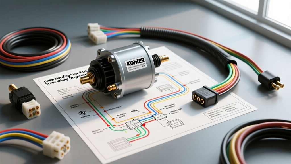
Introduction to Kohler Starter Circuits
Kohler engines, particularly the Command, Courage, and Aegis series, are the undisputed workhorses of the landscaping, agricultural, and utility vehicle world. Whether you are restoring a vintage John Deere garden tractor, rewiring a modern Cub Cadet zero-turn mower, or maintaining an industrial sweepers, understanding the Kohler starter wiring diagram is essential for reliable operation. For beginners, the maze of red, black, and yellow wires hidden beneath the dashboard or engine shroud can seem daunting. However, the underlying electrical logic is remarkably straightforward once broken down into fundamental circuits. This guide will demystify the starter circuit, providing actionable wiring advice, specific American Wire Gauge (AWG) requirements, and real-world troubleshooting insights.
Core Components of the Starter Circuit
Before tracing wires, you must understand the four primary components that make up the Kohler 12-volt starting system:
- The 12V Battery: The power source. Small engines typically require a minimum of 230 Cold Cranking Amps (CCA) to overcome engine compression.
- The Ignition Switch: A momentary contact switch. When turned to the 'Start' position, it sends a low-amperage signal to the solenoid.
- The Starter Solenoid: A heavy-duty electromagnetic relay. It acts as a bridge, allowing a small trigger wire to control the massive amperage required by the starter motor.
- The Starter Motor: The electric motor that physically turns the engine's flywheel via a Bendix drive or gear-reduction mechanism.
According to the SAE J1128 Low Tension Primary Cable Standard, routing high-amperage current through a dashboard ignition switch would require massive, impractical wiring and pose a severe fire hazard. The solenoid solves this by keeping the heavy-gauge battery cables as short as possible.
Decoding the Standard Kohler Starter Wiring Diagram
When visualizing a standard Kohler starter wiring diagram, imagine the flow of electrons in two distinct circuits: the high-current cranking circuit and the low-current control circuit.
The High-Current Cranking Circuit
This circuit handles anywhere from 150 to 300 amps during engine cranking. It begins at the positive terminal of the battery and travels via a thick, heavy-gauge red cable directly to one of the large threaded posts on the starter solenoid. A second, equally thick cable connects the opposite large threaded post on the solenoid directly to the B+ terminal on the starter motor. The circuit is completed through the engine block ground strap back to the negative battery terminal.
The Low-Current Control Circuit
This circuit handles less than 5 amps. Power flows from the battery to the 'B' (Battery) terminal on the back of the ignition switch. When the key is turned to 'Start', power exits the 'S' (Start) terminal and travels through the wiring harness to the small trigger post on the starter solenoid. This electromagnetic pulse pulls the internal copper disc, bridging the two large posts and engaging the starter motor.
Wire Gauge and Color Code Specifications
Using the correct wire gauge is critical. Undersized wires will cause severe voltage drop, resulting in a slow-cranking engine that fails to start, especially in cold weather. Below is the standard specification chart for Kohler-powered utility vehicles and tractors.
| Circuit Path | Recommended AWG Size | Typical OEM Color Code | Terminal / Connection Point |
|---|---|---|---|
| Battery (+) to Solenoid | 6 AWG or 8 AWG | Red | Battery Post to Solenoid Large Post A |
| Solenoid to Starter Motor | 6 AWG or 8 AWG | Red or Black | Solenoid Large Post B to Starter B+ Stud |
| Ignition Switch to Solenoid | 14 AWG or 12 AWG | Yellow or Red/White | Switch 'S' Terminal to Solenoid Small 'S' Post |
| Engine Ground Strap | 8 AWG or 6 AWG | Black or Bare Copper | Engine Block to Chassis / Battery (-) |
The Role of Safety Interlock Modules (SAM)
One of the most common mistakes beginners make when reading a basic Kohler starter wiring diagram is assuming the ignition switch connects directly to the solenoid. On modern equipment (such as John Deere, Toro, and Exmark), the trigger wire is routed through a Safety Interlock Module (SAM) or a series of mechanical relays.
The SAM is a solid-state logic board designed to prevent the engine from cranking or running under unsafe conditions. Before the 12V signal reaches the starter solenoid, the SAM verifies the status of several micro-switches:
- PTO (Power Take-Off) Switch: Must be disengaged (OFF).
- Brake Pedal Switch: Must be fully depressed.
- Seat Switch: Must detect operator weight (or PTO must be off if operator is absent).
- Transmission Levers: Must be in the neutral/parked position on zero-turn mowers.
If any of these conditions are not met, the SAM interrupts the low-current control circuit. The ignition switch sends power, but the solenoid never receives the trigger signal. When diagnosing a 'no-crank' issue, always consult the specific equipment manufacturer's wiring schematic to locate the SAM and test its input/output logic.
Step-by-Step Wiring and Torque Specifications
When replacing a solenoid or rewiring the starter circuit, follow these professional installation steps to ensure longevity and prevent electrical fires:
- Disconnect the Battery: Always remove the negative (-) battery cable first to prevent accidental short circuits.
- Clean the Terminals: Use a wire brush to clean the battery posts, solenoid studs, and starter B+ terminal. Bare, shiny metal is required for optimal conductivity.
- Mount the Solenoid: Ensure the solenoid is mounted to a clean, unpainted metal surface if it is a 3-post (ground-through-bracket) design. If using a 4-post design, connect the dedicated ground wire to a clean chassis ground.
- Apply Torque Specifications: Do not overtighten the nuts on the solenoid studs, as they can easily snap. For standard 5/16'-24 UNF nuts found on most small engine solenoids, apply 120 to 150 in-lbs of torque. For 3/8'-24 UNF nuts, torque to 180 to 220 in-lbs.
- Protect the Connections: Apply a liberal coat of dielectric grease or a dedicated battery terminal protectant spray over all threaded connections to prevent galvanic corrosion.
Troubleshooting the Starter Circuit
When a Kohler engine fails to start, use a digital multimeter (DMM) to isolate the fault. Avoid the 'guess and replace' method.
Symptom: Single 'Click' but No Cranking
This indicates the solenoid is receiving the trigger signal and pulling the internal plunger, but high-current flow is being restricted.
- Cause 1: Corroded Solenoid Contacts. Internal copper discs pit and burn over time. Fix: Replace the solenoid.
- Cause 2: Severe Voltage Drop. Fix: Perform a voltage drop test. Place your DMM leads across the two large solenoid posts while an assistant turns the key to 'Start'. A reading higher than 0.2V indicates high resistance inside the solenoid or at the cable crimps.
Symptom: Rapid Clicking
- Cause: Low Battery Voltage. The solenoid engages, but the massive current draw instantly drops the battery voltage below the solenoid's holding threshold, causing it to release. The cycle repeats rapidly. Fix: Load test and charge the battery.
Symptom: Complete Silence (No Click)
- Cause: Open Control Circuit. Power is not reaching the small trigger post. Fix: Check the main inline fuse (usually 20A or 30A). Test for 12V at the ignition switch 'B' terminal, then test for 12V at the 'S' terminal while cranking. Finally, verify the safety interlock switches and SAM module.
Final Thoughts on Kohler Wiring
Mastering the Kohler starter wiring diagram is a foundational skill for any small engine or utility vehicle technician. By respecting AWG requirements, understanding the critical role of safety interlock modules, and utilizing voltage drop testing instead of relying on visual inspections, you can reliably diagnose and repair starting faults. For model-specific pinouts and advanced diagnostic flowcharts, always refer to the official Kohler Engines Service Manuals corresponding to your exact engine specification number.