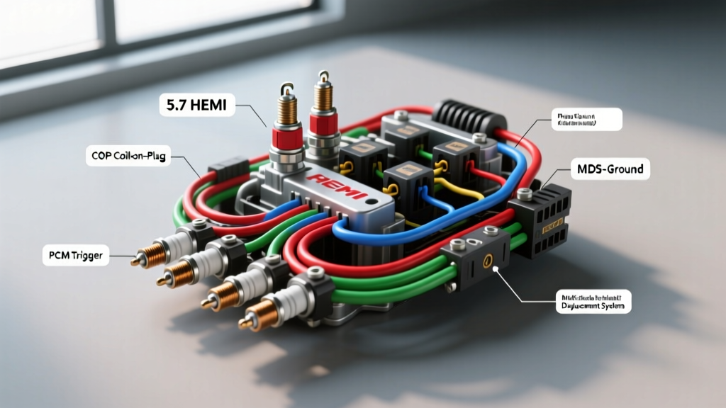
Understanding the 5.7L HEMI Ignition Architecture
When searching for a firing order 5.7 hemi spark plug wiring diagram, technicians and DIYers often expect to see traditional distributor routing or high-tension spark plug wires. However, the Chrysler/Dodge/Jeep/Ram 5.7L HEMI V8 utilizes a modern Coil-On-Plug (COP) ignition system. There are no traditional spark plug wires to route; instead, each of the eight cylinders features an individual ignition coil mounted directly over the spark plug, controlled by the Next Generation Controller (NGC) Powertrain Control Module (PCM).
This complete wiring diagram walkthrough will decode the 5.7L HEMI firing sequence, map the COP harness pinouts, explain the critical integration with the Multi-Displacement System (MDS), and provide actionable diagnostic steps for ignition-related misfires.
5.7 HEMI Firing Order and Cylinder Layout
The 5.7L HEMI V8 operates on a specific firing sequence designed to balance engine harmonics and optimize exhaust scavenging. The factory firing order is 1-8-4-3-6-5-7-2.
Understanding the physical cylinder layout is critical when diagnosing misfire codes (P0300-P0308) or tracing wiring harness faults back to the PCM.
- Left Bank (Driver Side): Cylinders 1, 3, 5, 7 (Odd)
- Right Bank (Passenger Side): Cylinders 2, 4, 6, 8 (Even)
Expert Note: The front of the engine (where the serpentine belt is located) is where Cylinders 1 and 2 are positioned. Cylinder 1 is on the driver's side front, and Cylinder 2 is on the passenger side front.
Multi-Displacement System (MDS) Cylinders
Unlike standard V8 engines, the 5.7L HEMI features MDS, which deactivates four specific cylinders under light-load cruising conditions to save fuel. The MDS-equipped cylinders are 1, 4, 6, and 7. These cylinders utilize specialized lifters, solenoids, and slightly different heat-range spark plugs in certain model years. The wiring for the MDS solenoids runs in the exact same engine harness loom as the COP wiring, which creates a unique failure mode we will address later.
Coil-On-Plug (COP) Wiring Diagram Walkthrough
Each ignition coil on the 5.7L HEMI connects to the engine wiring harness via a 2-pin weather-pack style connector. The NGC PCM uses a 'wasted spark' logic internally but fires the COP individually based on crankshaft and camshaft position sensor inputs.
Pinout Configuration (Typical 2-Pin Coil Connector)
- Pin 1 (ASD Feed): 12V Switched Power from the Automatic Shutdown (ASD) Relay. Wire Color: Dark Green/Orange (DG/OR). Wire Size: 14 AWG. This circuit provides the primary voltage required to saturate the coil winding.
- Pin 2 (PCM Trigger): Coil Driver Ground Signal. Wire Color: Varies by cylinder (see table below). Wire Size: 18 AWG. The PCM completes the ground circuit to fire the coil, then rapidly opens the circuit to collapse the magnetic field and generate the spark.
PCM to Coil Pack Signal Circuit Reference Table
The following table outlines the standard NGC PCM pinouts for the 5.7L HEMI COP trigger wires. Note that wire colors may vary slightly depending on the exact model year (e.g., 2003-2008 vs. 2009+ Eagle heads), but the PCM logic remains identical.
| Cylinder | Bank / Position | PCM Connector | PCM Pin | Trigger Wire Color | MDS Equipped? |
|---|---|---|---|---|---|
| 1 | Left / Front | C1 (38-Way) | Pin 14 | Brown/White (BR/WT) | Yes |
| 2 | Right / Front | C1 (38-Way) | Pin 15 | Dark Blue/White (DB/WT) | No |
| 3 | Left / Mid-Front | C1 (38-Way) | Pin 16 | Dark Green/White (DG/WT) | No |
| 4 | Right / Mid-Front | C1 (38-Way) | Pin 17 | Yellow/White (YL/WT) | Yes |
| 5 | Left / Mid-Rear | C1 (38-Way) | Pin 18 | Purple/White (PU/WT) | No |
| 6 | Right / Mid-Rear | C1 (38-Way) | Pin 19 | Light Green/White (LG/WT) | Yes |
| 7 | Left / Rear | C1 (38-Way) | Pin 20 | Orange/White (OR/WT) | Yes |
| 8 | Right / Rear | C1 (38-Way) | Pin 21 | Light Blue/White (LB/WT) | No |
Ignition Harness Troubleshooting & Real-World Failure Modes
As an automotive electrical expert, I see the same 5.7L HEMI ignition harness issues repeatedly in the shop. If you are diagnosing a random or specific cylinder misfire, follow this decision tree before condemning a coil or spark plug.
1. The Rear Valve Cover Chafe Point
The main engine harness routes tightly across the rear of the intake manifold and valve covers. Over time, engine torque roll and heat cause the split-loom tubing to degrade. The harness rubs against the aluminum cylinder head or the rear lifting bracket. Failure Mode: The 18 AWG COP trigger wires or the 14 AWG ASD feed chafes to ground. If a trigger wire chafes to ground, the PCM sees a short circuit and will shut down the coil driver to protect the internal transistor, resulting in a dead cylinder and a P035X code.
2. MDS Solenoid Wiring Interference
Because the MDS solenoid wiring shares the same harness branch as the rear COP wiring, a chafed harness can cause a COP trigger wire to short into an MDS solenoid control wire. Symptom: The vehicle throws a misfire code alongside a P3400-series MDS solenoid code. The PCM attempts to fire Cylinder 7, but the voltage bleeds into the MDS solenoid circuit, causing a partial lifter collapse and a severe mechanical ticking noise.
3. Testing the ASD Feed and Ground Trigger
Do not use a standard test light on the 18 AWG PCM trigger wire; the incandescent bulb can draw enough current to fry the NGC PCM's internal driver. Instead, use a digital logic probe or a dedicated COP tester.
- Step 1: Backprobe Pin 1 (DG/OR) with a Digital Multimeter (DMM). With the key ON, ENGINE OFF (KOEO), you should read battery voltage (12.2V - 12.6V). If 0V, check the ASD Relay and TIPM (Totally Integrated Power Module).
- Step 2: Connect a logic probe to Pin 2 (Trigger). Crank the engine. The logic probe should pulse rapidly. If it stays solid high or solid low, the wire is open or shorted between the coil and PCM Connector C1.
- Step 3: Perform a voltage drop test on the coil ground circuit. The COP system relies on the PCM to provide the ground path; ensure the PCM chassis grounds on the passenger side cylinder head are clean and torqued to 105 in-lbs.
Spark Plug Replacement & Torque Specifications
Proper spark plug installation is just as critical as the wiring. According to NGK Spark Plug technical documentation, the 5.7L HEMI requires specific plugs to manage the high-combustion chamber temperatures and MDS transitions.
- OEM Part Number: Champion REC14MCC4 (Copper Core) or NGK LZFR5C-11.
- Spark Plug Gap: 0.040 inches (1.02 mm). Do not attempt to adjust the gap on iridium or platinum fine-wire plugs, as you risk snapping the center electrode.
- Thread Lubrication: Apply a single drop of high-temp copper anti-seize to the plug threads. Warning: If using NGK plugs with a pre-applied zinc-chromate coating, install them dry to prevent over-torquing.
- Torque Specification: 14 lb-ft (19 Nm). The HEMI uses aluminum cylinder heads with tapered-seat spark plugs. Over-torquing will stretch the aluminum threads, leading to compression loss and blown-out plugs.
- Dielectric Grease: Apply a thin layer of silicone dielectric grease to the inside of the COP rubber boot. This prevents moisture intrusion, stops the boot from bonding to the ceramic insulator, and prevents secondary voltage from arcing to the aluminum cylinder head.
Summary
Mastering the 5.7 HEMI firing order and COP wiring diagram requires understanding the NGC controller's ground-trigger logic and the physical routing vulnerabilities of the engine harness. By referencing the correct PCM pinouts, utilizing safe diagnostic tools like logic probes, and adhering to strict torque specifications, you can accurately diagnose and repair HEMI ignition faults without causing collateral damage to the PCM or cylinder heads. For deeper OEM schematic references, technicians should consult Mopar Tech Authority or review SAE International ignition standards for low-tension circuit testing protocols.