Why GMT800 Trucks Need a Wiring Diagram and Relay Upgrade
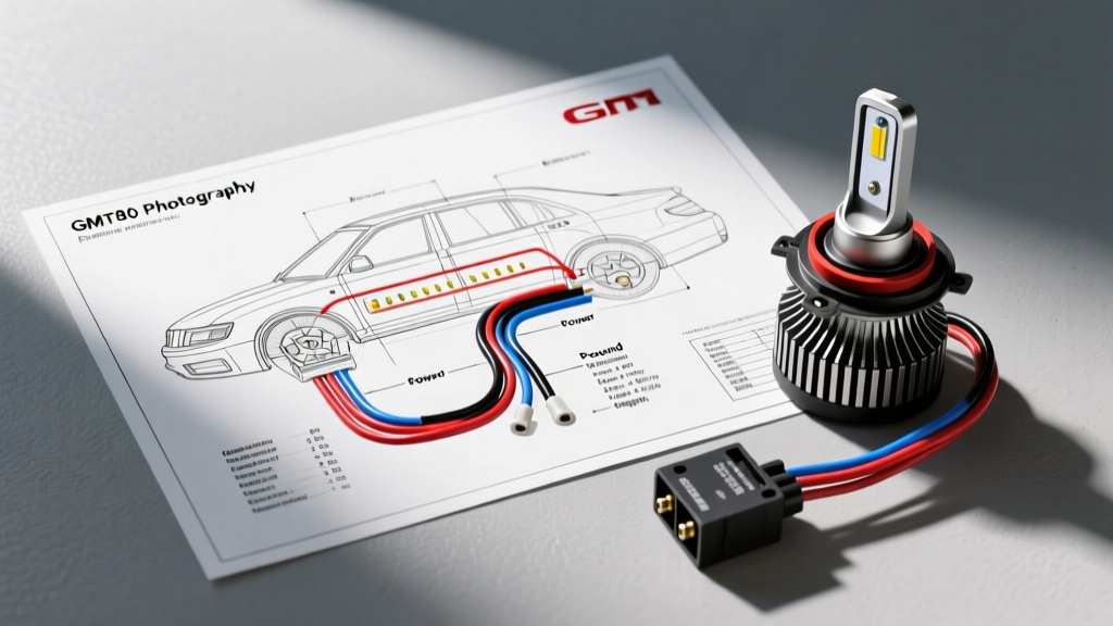
If you own a 1999-2006 GM GMT800 platform truck (Silverado, Sierra, Tahoe, or Suburban), you have likely experienced the notorious 'dim headlight' syndrome or noticed the headlight switch connector melting. This is not a coincidence; it is a direct result of the factory electrical routing. To properly diagnose and fix this issue, a thorough understanding of the GM headlight wiring diagram is mandatory before cutting, splicing, or installing an aftermarket relay harness.
From the factory, GM routes the main 12V power from the under-hood fuse block, through the firewall bulkhead connector, into the cabin to the headlight switch, and then back out through the firewall to the headlight bulbs. This creates a circuit path exceeding 30 feet in length. According to the principles of electrical resistance, pushing 10 to 15 amps of current through 14 AWG wire over that distance results in a severe voltage drop. By the time the current reaches the halogen or HID bulbs, voltage often sags below 11.5V, resulting in poor light output and excess heat generated at the switch terminals.
By utilizing a heavy-duty relay harness, we bypass the OEM switch for the high-current load. The headlight switch is relegated to a low-current 'trigger' role, extending its lifespan and delivering a full 13.8V+ directly from the alternator to the bulbs. However, installing a relay harness blindly without referencing the specific GM headlight wiring diagram will lead to conflicts with the Daytime Running Lamp (DRL) module, flash-to-pass circuits, and automatic headlight systems.
Decoding the OEM GM Headlight Wiring Diagram
Before tapping into any wires, you must identify the correct trigger circuits. The GMT800 headlight switch utilizes a multi-pin connector. Below is the critical pinout and wire color reference derived from the OEM GM service documentation. Note that wire colors can occasionally vary by exact model year and trim, so verifying with a multimeter is always recommended.
| Pin | Wire Color | AWG Size | Function |
|---|---|---|---|
| A | Yellow | 12 GA | 12V Battery Feed (Main Power to Switch) |
| B | Tan | 14 GA | Low Beam Feed (Trigger) |
| C | Light Green | 14 GA | High Beam Feed (Trigger) |
| D | Black | 14 GA | Switch Ground |
| E | Brown | 18 GA | Parking Lamps Feed |
| F | White | 18 GA | Instrument Panel Illumination |
For a standard headlight relay upgrade, you will only be interacting with the Tan (Low Beam) and Light Green (High Beam) wires. These wires will serve as the low-amperage trigger signals for your new relays.
The DRL Complication: What the Diagram Doesn't Tell You
The most common failure point during a GM headlight relay harness installation involves the Daytime Running Lamp (DRL) system. On GMT800 trucks, the DRLs are not separate bulbs; they utilize the high-beam bulbs operating at a reduced voltage. GM achieves this either through a Pulse Width Modulation (PWM) signal or a high-resistance DRL relay/resistor located under the hood.
If you simply splice your new relay harness trigger into the Light Green high-beam wire without accounting for the DRL backfeed, the PWM signal can cause your new relays to chatter, overheat, or remain stuck in the 'on' position. When referencing the full GM headlight wiring diagram, you must locate the DRL relay (usually in the under-hood fuse block) and ensure your trigger wire is spliced on the bulb side of the DRL module, or install a diode on the trigger wire to prevent the DRL module's reduced voltage from energizing your heavy-duty 40A relays.
Step-by-Step Relay Harness Installation Guide
Step 1: Mapping and Testing the Trigger Wires
Using a digital multimeter, back-probe the Tan and Light Green wires at the back of the headlight switch connector or at the closest accessible bulkhead junction. Set your multimeter to DC Voltage. With the engine running (to simulate DRL operation), note the voltage on the Light Green wire. If it reads around 6V-9V, that is your DRL PWM signal. Turn the headlight switch to 'High Beam'. The voltage should jump to a solid 13.5V+. This confirms you have the correct wire for the high-beam relay trigger.
Step 2: Routing the 10 AWG Power and Ground
A proper relay harness uses 10 AWG primary wire for the main battery feed and ground. Route the main power wire from the positive battery terminal, ensuring it is encased in split-loom tubing and secured away from exhaust manifolds and steering shafts. Install an inline 30A MAXI fuse within 6 inches of the battery terminal. For the ground, do not rely on the radiator core support, which often suffers from poor conductivity due to paint and corrosion. Scrape the paint down to bare metal on the inner fender or engine block, apply a dab of dielectric grease after bolting, and use a star washer to bite into the metal.
Step 3: Splicing with Metri-Pack Connectors
Avoid using generic 'scotch-lock' T-taps. They are notorious for severing OEM wire strands and allowing moisture ingress, leading to copper oxidation. Instead, use the OEM-style Delphi/Aptiv Metri-Pack 280 series splice connectors. Strip the OEM Tan wire, crimp the Metri-Pack terminal using a proper ratcheting crimper, and perform a 10-lb pull test to ensure mechanical integrity. Seal the connection with 3M adhesive-lined marine heat shrink to prevent capillary action from drawing water into the harness.
Real-World Troubleshooting: Flash-to-Pass and Auto-Lamps
After installation, test the 'Flash-to-Pass' feature on the turn signal stalk. In the GM headlight wiring diagram, the flash-to-pass circuit bypasses the headlight switch entirely, feeding 12V directly to the high-beam bulbs via the multifunction switch. If your new relays do not trigger during flash-to-pass, your trigger splice is located on the wrong side of the multifunction switch junction. You must move your trigger tap closer to the headlight bulbs or directly at the firewall bulkhead connector (Connector C100/C305 depending on the exact year) to capture both the headlight switch signal and the flash-to-pass signal simultaneously.
Furthermore, if your truck is equipped with the 'Auto-Lamp' feature (twist the switch to the 'AUTO' detent), the Body Control Module (BCM) controls the ground side of the headlight switch relay. Ensure your aftermarket relay harness triggers are wired to the positive feed side, as the BCM switching the ground will not provide the 12V+ required to energize a standard automotive 4-pin relay coil.
Authoritative References & Standards
When modifying automotive lighting circuits, adherence to industry standards ensures safety and longevity. The wire specifications used in this guide align with SAE J1128 Low Tension Primary Cable standards, which dictate the thermal and abrasion resistance requirements for under-hood wiring. For complete, model-year-specific factory schematics, technicians should consult the official service manuals published by Helm Incorporated, the authorized publisher for General Motors service documentation. Always verify your specific RPO (Regular Production Option) codes, as vehicles with Z71 off-road packages or specific upfitter packages may feature altered lighting harnesses.