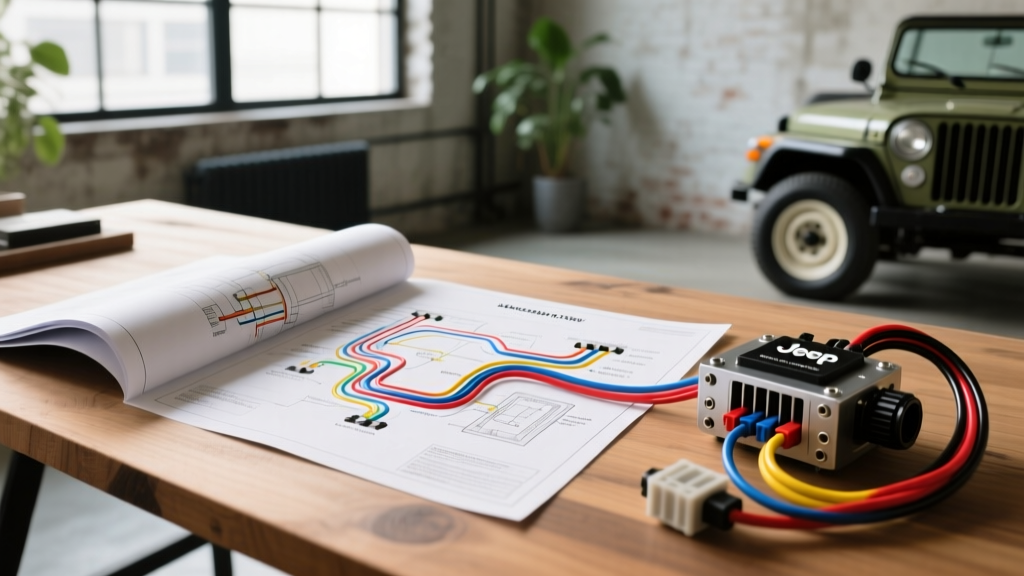
Why the Original Jeep CJ5 Wiring Diagram PDF is Your Best Baseline
When undertaking a modern powertrain swap in a classic Jeep, finding a reliable Jeep CJ5 wiring diagram PDF is the critical first step. Whether you are dropping in a GM LS, a Ford Coyote, or upgrading the factory AMC 304/360 to electronic fuel injection (EFI), the original factory schematic serves as your roadmap. The CJ5, produced through 1983, features an electrical architecture designed for low-amperage carbureted engines and basic lighting. Modern EFI systems, high-pressure fuel pumps, and electric cooling fans demand significantly more current and cleaner voltage signals than the factory harness can provide.
Relying solely on an aftermarket universal harness without referencing the OEM diagram often leads to integration failures at the firewall bulkhead, improper gauge cluster signaling, and dangerous voltage drops. By cross-referencing your aftermarket EFI manual (such as those from Howell or Painless Performance) with the factory Jeep CJ5 wiring diagram PDF, you can safely merge modern high-current circuits with the classic CJ5 chassis.
Decoding the Factory CJ5 Firewall Bulkhead Connector
The most daunting part of any CJ5 restomod is the firewall bulkhead connector. Early to mid-1970s CJ5 models utilized a 14-pin round bulkhead connector, while later models transitioned to a larger rectangular multi-plug. For this upgrade guide, we will focus on the classic 14-cavity round connector, which is the most common starting point for restomod projects.
When integrating an EFI harness, you must bypass the factory ignition and battery feed pins to prevent overloading the 40-year-old copper traces. Below is the pinout mapping for the standard 14-pin CJ5 firewall connector.
| Cavity | Wire Color | AWG | Function / Circuit | EFI Swap Action |
|---|---|---|---|---|
| 1 | Red | 10 | Battery Feed to Fuse Box | Bypass; run new 8 AWG direct from battery |
| 2 | Black | 12 | Main Ground | Retain; upgrade to 8 AWG star ground |
| 3 | Yellow | 14 | Dimmer Switch Feed | Retain for lighting circuit |
| 4 | Green | 16 | Right Front Turn/Marker | Retain |
| 5 | White | 16 | Left Front Turn/Marker | Retain |
| 6 | Blue | 14 | High Beam Indicator | Retain |
| 7 | Red/White | 14 | Ignition Switch 'Start' | Tap for EFI starter signal relay |
| 8 | Brown | 14 | Ignition Switch 'Run' | Tap for EFI main relay trigger |
| 9 | Orange | 16 | Oil Pressure Sender | Retain for factory gauge cluster |
| 10 | Tan | 16 | Water Temp Sender | Retain; add EFI coolant temp sensor |
Integrating the EFI Main Power and Relays
Modern EFI ECUs require a stable 12V+ supply with less than 0.5V of drop. The factory CJ5 ignition switch and bulkhead connector cannot handle the 25-30 amp continuous draw of an ECU, injectors, and high-pressure fuel pump. Using your Jeep CJ5 wiring diagram PDF, locate the Brown 'Run' wire (Cavity 8) at the steering column.
Instead of feeding the EFI harness directly from this wire, use the Brown wire solely as a low-amperage trigger signal for a continuous-duty 40A Bosch-style ISO relay. Mount the relay on the inner fender, close to the battery. Run a new 8 AWG XLPE (cross-linked polyethylene) insulated wire from the battery positive terminal, through a 50A Mega Fuse, directly to Pin 30 of the relay. Pin 87 will then feed the EFI harness main power distribution block. This ensures the ECU receives clean, unfiltered battery voltage, preventing the erratic idle and misfire codes common in poorly wired swaps.
The Ammeter Bypass and High-Amp Alternator Upgrade
If you are upgrading to a modern EFI system, you are likely also upgrading the charging system to a 100A+ alternator (such as a GM CS130D or Denso unit). The factory CJ5 ammeter is a notorious failure point; it routes the entire alternator output through the dashboard gauge via 10 AWG wires and aging spade connectors. This creates a massive voltage drop and a severe fire hazard.
According to Mad Electrical, the safest and most efficient upgrade is the 'Ammeter Bypass'. Disconnect the two large 10 AWG red wires from the back of the factory ammeter and join them using a heavy-duty copper crimp sleeve and adhesive-lined heat shrink. This effectively converts the dash wiring into a heavy-duty junction block. Next, run a 4 AWG welding cable directly from the alternator output stud to the starter solenoid battery post. For detailed alternator wiring pinouts and gauge recommendations, always refer to SAE J1128 standards for low-tension primary cable specifications.
To retain charging system monitoring, install a modern digital voltmeter in a blank dash switch hole, wiring it to a switched 12V source and a clean chassis ground.
Headlight Circuit Relay Modification
The CJ5 factory headlight switch routes full headlight current (approx. 12-15 amps) directly through the dashboard switch and the firewall bulkhead. Over time, the internal contacts corrode, resulting in dim lights and melted switches. Using the wiring diagram, locate the Yellow feed wire and the Red/Black tracer wires exiting the headlight switch.
Upgrade this circuit by installing a dual-headlight relay harness. Wire the relay coil triggers to the factory headlight switch output. Run 12 AWG power feeds directly from the battery to the relay Pin 30 terminals, and use 14 AWG wires from Pin 87 to the headlight bulbs. This modification reduces voltage drop at the bulbs from an average of 2.5V down to less than 0.2V, drastically improving nighttime visibility without altering the exterior aesthetic.
Star Grounding Strategy for Modified Tubs
The CJ5 body tub is mounted to the frame via rubber isolators, meaning the tub has no inherent electrical ground. The factory relied on a single, often corroded, braided strap. When adding EFI sensors, digital gauges, and high-draw lighting, a poor ground will cause ECU sensor skew and erratic gauge behavior.
Implement a 'Star Ground' system. Fabricate a central ground bus bar mounted to the firewall or inner fender using stainless steel hardware. Run individual 12 AWG ground wires from the ECU, fuel pump relay, and gauge cluster to this bus bar. Finally, connect the bus bar to the engine block and the chassis frame using 2 AWG tinned copper braided straps. Always use star washers to bite through paint and primer, and coat the connections with Noalox anti-oxidant paste to prevent galvanic corrosion between dissimilar metals.
Final Harness Routing and Protection
When routing your new EFI harness through the CJ5 firewall, avoid the sharp edges of the factory sheet metal. Use a rubber grommet and apply dielectric grease to ease the harness through. Secure the loom using UV-resistant nylon cable ties and adhesive-backed mounts, keeping wiring at least 6 inches away from exhaust headers. For comprehensive harness routing and loom protection standards, consult the technical bulletins provided by Painless Performance Products. By methodically merging the data from your Jeep CJ5 wiring diagram PDF with modern electrical best practices, your classic Jeep will feature a reliable, fire-safe, and high-performance electrical system capable of supporting any modern powertrain.