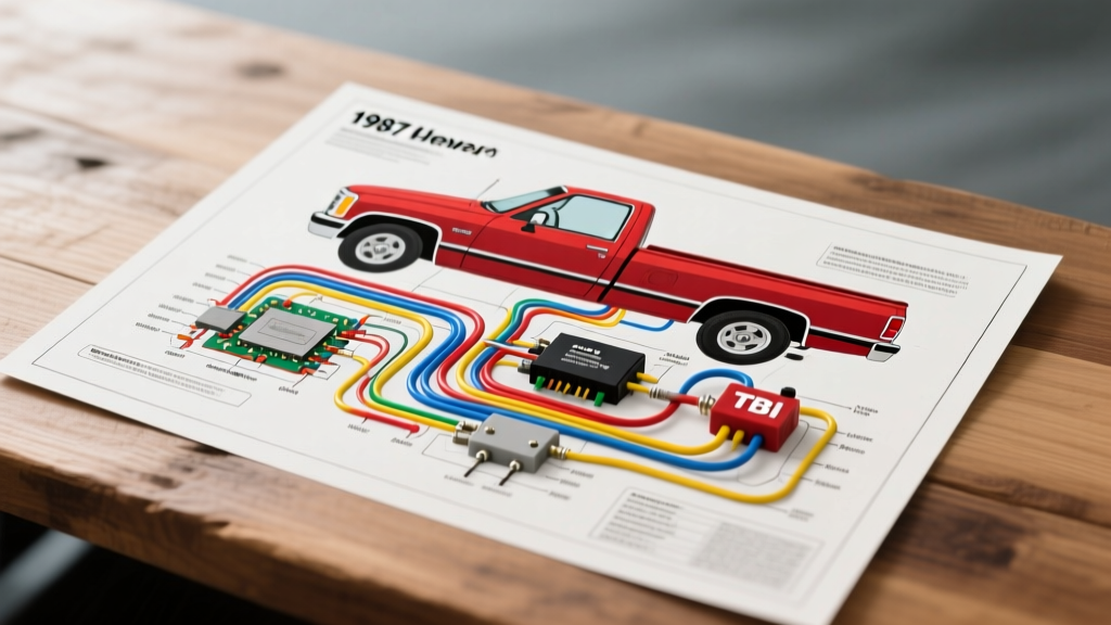
Mastering the 1987 Chevy Truck Wiring Diagram PDF for TBI Systems
The 1987 model year represents a pivotal transition for Chevrolet's C/K series 'Square Body' trucks. While inline-six models largely retained their carbureted setups, the 5.0L (305ci) and 5.7L (350ci) V8 engines were equipped with Throttle Body Injection (TBI). When sourcing a reliable 1987 Chevy truck wiring diagram PDF, technicians must pay close attention to the newly introduced Electronic Control Module (ECM) circuits, specifically the fuel delivery and sensor feedback loops. Unlike older, purely mechanical systems, the TBI harness relies on a precise 2-second prime cycle, relay logic, and a unique oil-pressure bypass circuit to manage fuel delivery.
This step-by-step troubleshooting flow is designed for automotive electricians and DIY restorers dealing with the most common 1987 C10/K10 fuel system failure: a no-start condition caused by a lack of fuel pump prime. By following this diagnostic tree and referencing GM circuit numbers, you can isolate faults in the relay, the ECM driver, or the tank selector valve without throwing unnecessary parts at the vehicle.
How to Read the GM 1987 Schematic Standards
Before probing connectors, it is vital to understand how General Motors formatted their wiring diagrams in the late 1980s. According to the GM Heritage Center Vehicle Information Kits, wire colors are abbreviated using a two-letter code (e.g., DK GRN/WHT for Dark Green with a White tracer). Circuit numbers are printed on the wire insulation and correspond directly to the factory diagram. Furthermore, GM utilized Delphi Weather-Pack connectors for under-hood sensors and relays, which are prone to terminal oxidation if the dielectric grease was omitted during previous services.
Step-by-Step Troubleshooting Flow: No Fuel Pump Prime
When you turn the ignition key to the 'ON' position, the ECM should ground the fuel pump relay for exactly two seconds to prime the TBI injectors. If the engine cranks but does not fire, and you hear no hum from the fuel tank, follow this diagnostic sequence.
Step 1: Verify the Fuel Pump Relay and Prime Circuit
The fuel pump relay on a 1987 Chevy truck is typically mounted on the passenger side inner fender well or near the junction block. It is a standard 4-pin ISO-style relay.
- Test A (Power Feed): Using a digital multimeter (DMM), back-probe Terminal 30 (Orange wire, 12 AWG). You should read battery voltage (12.2V - 12.6V) at all times. If 0V, check the fusible link near the starter solenoid.
- Test B (Ignition Feed): Back-probe Terminal 85 (Pink/Black wire, 18 AWG). With the key in the 'RUN' position, you must read 12V. This circuit feeds through the ignition switch and the oil pressure switch parallel loop.
- Test C (ECM Prime Ground): Connect a test light between Terminal 86 (Dark Green/White wire, 18 AWG) and the positive battery terminal. Have an assistant turn the key to 'ON'. The test light should illuminate for exactly 2 seconds. If it stays on, the ECM driver is shorted to ground. If it never illuminates, the ECM is not triggering the relay (check ECM Pin A7).
Step 2: Test the Oil Pressure Sender Bypass Circuit
A unique quirk of the 1987 Chevy TBI wiring is the oil pressure switch bypass. GM designed this so that if the fuel pump relay fails, the truck will still run once oil pressure builds. The switch, located behind the distributor, has three terminals: one for the dash gauge, one for ground, and one for the fuel pump bypass.
- Symptom: The truck cranks for 5-10 seconds before starting, or only starts if you hold the key in the 'START' position.
- Diagnosis: Locate the Tan/White wire (18 AWG) running from the oil pressure switch to the fuel pump relay Terminal 85 circuit. With the engine cranking, measure voltage on this wire. If you have 12V while cranking but the pump doesn't run, the tank selector switch or the pump ground is at fault. If the truck starts only after oil pressure reaches 4 PSI, your fuel pump relay is faulty, and the ECM prime circuit is failing.
Step 3: Inspect the Dual-Tank Selector Valve (If Equipped)
Many 1987 C/K trucks feature dual fuel tanks. The dashboard selector switch sends 12V to a motorized valve on the driver-side frame rail, which physically routes the fuel and completes the electrical circuit to the correct tank sender.
- Power In: Pink wire (14 AWG) from the ignition fuse.
- Front Tank Out: Light Blue wire (14 AWG).
- Rear Tank Out: Dark Blue wire (14 AWG).
- Failure Mode: If the valve motor binds due to corrosion, the internal micro-switches will not close, cutting power to the fuel pump entirely. Bypass the valve temporarily by jumping the Pink wire to the Light Blue wire at the frame rail connector to verify pump operation.
Step 4: Verify ECM Grounds and ALDL Diagnostics
The Delco ECM (typically part number 1227747 for 1987 V8s) requires pristine grounds to trigger the fuel pump relay. Poor grounds cause erratic injector pulse and relay dropouts.
- G102: Located on the right side of the engine block, near the cylinder head.
- G103: Located on the intake manifold, near the TBI base. This is the primary logic ground for the ECM. Clean this terminal with a wire brush and apply dielectric grease.
- ALDL Prime Test: Locate the 12-pin Assembly Line Diagnostic Link (ALDL) under the dash. By inserting a jumper wire between Pin A (Ground) and Pin G (Fuel Pump Test), you can manually energize the fuel pump relay, bypassing the ECM entirely. If the pump runs with the jumper but not via the ECM, the 7747 module is likely compromised.
1987 Chevy TBI Fuel Pump Wiring Specification Chart
| Circuit / Component | Wire Color | AWG Size | Function & Routing |
|---|---|---|---|
| Relay Terminal 30 | Orange | 12 AWG | Constant 12V Battery Feed from Fusible Link |
| Relay Terminal 87 | Gray | 12 AWG | Switched 12V to Fuel Pump / Tank Selector |
| Relay Terminal 85 | Pink/Black | 18 AWG | Ignition Switched 12V & Oil Pressure Bypass |
| Relay Terminal 86 | Dark Green/White | 18 AWG | ECM Pin A7 Ground Control (2-Sec Prime) |
| Oil Press Switch Bypass | Tan/White | 18 AWG | 12V Output when Oil Pressure > 4 PSI |
| ALDL Pin G | Gray/Black | 18 AWG | Fuel Pump Diagnostic Prime Trigger |
Common Failure Modes in '87 Square Body Harnesses
Based on decades of field diagnostics and data referenced in Haynes Chevrolet Pick-Ups Repair Manuals, the 1987 C/K harness suffers from a few specific age-related failures:
- Bulkhead Connector Corrosion: The main firewall bulkhead connector (located on the driver's side) is notorious for accumulating moisture. The heavy 10 AWG and 12 AWG power feeds for the accessories and fuel system can overheat and melt the plastic housing, causing voltage drops that prevent the fuel pump from reaching its required 9-13 PSI operating pressure.
- Brittle Loom Near the TBI: The high ambient heat from the exhaust crossover and the TBI body causes the corrugated plastic loom and the underlying PVC wire insulation to become brittle. Inspect the injector harness (Dark Blue and Dark Green wires) for micro-fractures that cause short-to-ground when the engine torques under load.
- Tank Sender Ground Rot: The fuel pump/sender assembly grounds to the frame rail near the tank strap. On K-series (4WD) trucks, mud and road salt trap moisture against this ring terminal, leading to galvanic corrosion. Always verify pump ground continuity to the bare frame before condemning the pump motor.
Authoritative References & Standards
When performing deep-level harness repairs, always adhere to OEM crimping and splicing standards. According to SAE International Standard J1128 for low-tension primary automotive cable, any splices made in the 12 AWG fuel pump feed must utilize sealed, adhesive-lined heat shrink crimps to prevent capillary action from drawing moisture into the copper strands. Never use twist-connectors or electrical tape on under-carriage fuel circuits. For exact pinout diagrams and circuit routing numbers specific to your VIN, consult the factory GM Service Manual or a verified 1987 Chevy truck wiring diagram PDF from the GM Heritage archives.