Understanding the 4.3L MerCruiser Starting Circuit Architecture
Wiring a marine starter differs fundamentally from automotive applications due to the harsh, high-humidity, and salt-laden environments inherent to boating. The 4.3L MerCruiser V6 engine relies on a robust starting circuit designed to mitigate voltage drop over long cable runs from the helm to the transom. Unlike standard automotive setups that route ignition switch current directly to the starter solenoid, most 4.3 MerCruiser configurations utilize a heavy-duty slave solenoid (starter relay) mounted on the engine block or bell housing. This architecture ensures that the high-amperage draw required to engage the starter drive gear is handled locally, while the helm-mounted ignition switch only carries a low-amperage control signal.
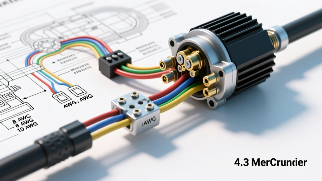
When referencing a 4.3 Mercruiser starter wiring diagram, technicians must identify whether the system uses a direct-drive solenoid or a slave solenoid setup. The slave solenoid acts as a high-current gatekeeper. When you turn the key to the 'Start' position, the ignition switch sends a 12V signal through a Yellow/Red (or sometimes solid Yellow) control wire to the 'S' (Start) terminal on the slave solenoid. The slave solenoid then bridges the main battery positive cable directly to the starter motor's own solenoid, cranking the engine. This guide details the practical, step-by-step installation and wiring of this critical marine circuit.
Marine-Grade Wiring Specifications and Materials
Using standard automotive copper wire in a marine environment will result in rapid galvanic corrosion (black wire disease), leading to high resistance and starting failure. All wiring must comply with ABYC E-11 AC and DC Electrical Systems on Boats standards. Below is the mandatory specification chart for a 4.3L MerCruiser starter installation.
| Circuit Segment | Wire Gauge (AWG) | Wire Type | Terminal Type | Overcurrent Protection |
|---|---|---|---|---|
| Battery to Slave Solenoid | 2 AWG or 4 AWG | UL 1426 Tinned Copper | 3/8" Ring Terminal (Heavy Duty) | 125A DC Marine Circuit Breaker |
| Slave Solenoid to Starter 'B' Terminal | 4 AWG | UL 1426 Tinned Copper | 3/8" Ring Terminal | None (Protected upstream) |
| Ignition Switch to Slave Solenoid 'S' | 10 AWG or 12 AWG | UL 1426 Tinned Copper | 10-32 Spade / Ring Terminal | Inline 15A ATO Fuse or Breaker |
| Starter Motor Ground Return | 2 AWG or 4 AWG | UL 1426 Tinned Copper | 3/8" Ring Terminal | N/A (Direct to Engine Block) |
Step-by-Step Starter and Slave Solenoid Installation
Step 1: Main Power Routing and Circuit Protection
Before running any cables, disconnect the negative battery terminal to prevent accidental shorting. According to ABYC standards, overcurrent protection must be installed within 7 inches of the battery's positive terminal. Install a 125A marine-grade ignition-protected circuit breaker on the positive battery post. From the load side of the breaker, route a 2 AWG tinned copper cable through the bilge and up to the engine compartment. Use corrugated split loom tubing to protect the cable from chafing against the fiberglass hull or engine mounts. Terminate the cable with a heavy-duty, adhesive-lined heat shrink 3/8" ring terminal. Crimp using a calibrated ratcheting crimper to ensure a cold-weld connection, then apply heat until the adhesive seals the wire insulation.
Step 2: Wiring the Slave Solenoid and Starter Motor
Mount the heavy-duty slave solenoid to the designated bracket on the 4.3L engine block. Connect the 2 AWG main power cable from the battery to the large input stud on the slave solenoid. Next, fabricate a short 4 AWG jumper cable to connect the large output stud of the slave solenoid to the 'B' (Battery) terminal on the starter-mounted solenoid. Torque the 3/8" nuts on these large studs to 12-15 ft-lbs. Over-tightening can strip the brass threads inside the solenoid housing, while under-tightening will cause arcing and melted terminals under high cranking loads. Connect the 4 AWG ground cable from the starter housing ground lug directly to a clean, bare-metal grounding pad on the 4.3L cylinder block.
Step 3: Ignition Switch and Control Circuit Integration
The control circuit triggers the slave solenoid. Run a 10 AWG tinned copper wire from the 'Start' terminal on your helm-mounted ignition switch. In MerCruiser harnesses, this wire is typically coded Yellow with a Red stripe (Y/R). Route this wire through the main engine harness grommet to prevent water intrusion into the cabin. Connect the Y/R wire to the small 'S' (Start) terminal on the slave solenoid. The other small terminal on the slave solenoid is the ground trigger; connect this to a verified clean engine block ground using a 12 AWG Black wire. Finally, ensure the 'I' (Ignition) terminal on the starter solenoid is left disconnected on modern EFI 4.3L models, as the ECM handles ignition timing and coil dwell independently of the starter bypass circuit used in older carbureted distributors.
Terminal Pinout and Wire Color Reference
Proper identification of OEM MerCruiser wire colors is critical for troubleshooting and re-pinning connectors. Reference the following color codes when interfacing with the factory harness:
- Red: Unswitched Battery Positive (12V+ Constant)
- Black: Main DC Ground / Engine Block Return
- Purple: Switched Ignition Hot (12V+ in 'Run' and 'Start' positions)
- Yellow/Red (Y/R): Starter Solenoid Engage Signal (12V+ only in 'Start' position)
- Yellow/Black: Ignition Kill / Ground-to-Stop Circuit (Carbureted models)
Troubleshooting Common MerCruiser Starting Faults
When the 4.3 MerCruiser fails to crank, use this diagnostic decision tree to isolate the electrical fault before replacing the starter motor.
Symptom: Single loud 'clunk' from the engine bay, but engine does not turn over.
- Cause A: Slave solenoid is engaging, but voltage drop across the main power cable is too high to spin the starter motor under load.
- Fix: Perform a voltage drop test. Place multimeter probes on the battery positive post and the starter 'B' terminal while an assistant cranks the engine. A reading higher than 0.5V indicates corroded terminals, an undersized AWG cable, or a failing 125A circuit breaker.
- Cause B: Starter motor internal armature short or worn carbon brushes.
- Fix: Bypass the slave solenoid by momentarily jumping the two large studs with an insulated screwdriver. If the starter spins freely without the engine load but fails under compression, replace the starter drive or motor.
Symptom: Rapid clicking from the slave solenoid, starter does not engage.
- Cause: Insufficient amperage reaching the slave solenoid 'S' terminal. The helm ignition switch contacts are worn, or the 10 AWG Y/R control wire has high resistance due to bilge moisture corrosion.
- Fix: Check voltage at the 'S' terminal during the crank attempt. If voltage drops below 9.5V, trace the Y/R wire back to the helm. Clean the ignition switch spade connectors and apply dielectric grease to prevent future oxidation.
Symptom: Starter motor spins, but does not engage the flywheel (freewheeling).
- Cause: The Bendix drive gear is seized on the starter motor armature shaft due to marine salt spray intrusion, or the flywheel ring gear has stripped teeth.
- Fix: Remove the starter motor. Inspect the flywheel teeth through the bell housing inspection cover. If the flywheel is intact, replace the starter motor with a marine-specific sealed unit (SAE J1171 compliant) to prevent internal salt corrosion.
Authoritative References and Standards
Proper marine electrical work requires adherence to strict safety and engineering standards to prevent electrical fires and galvanic corrosion. The procedures and specifications detailed in this guide are derived from the following authoritative marine electrical resources:
- American Boat and Yacht Council (ABYC) E-11 Standard: AC & DC Electrical Systems on Boats - Governs overcurrent protection placement, wire ampacity derating in engine spaces, and marine-grade material requirements.
- SAE J1128: Low Tension Primary Cable - Details the insulation thickness, temperature ratings, and copper stranding requirements for automotive and marine low-voltage wiring.
- Mercury Marine Service Manuals and OEM Wiring Schematics - Provides the definitive wire color codes, torque specifications, and slave solenoid configurations for the 4.3L V6 MerCruiser engine family.
By adhering to these OEM diagrams and marine electrical standards, you ensure reliable starting performance and long-term corrosion resistance for your 4.3 MerCruiser powertrain.