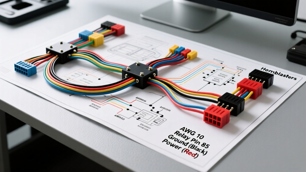
Understanding the Hornblasters Air Horn Circuit
Installing a HornBlasters air horn kit, such as the Shocker XL or the Conductor's Special, fundamentally transforms your vehicle's acoustic presence. However, integrating high-draw pneumatic components into a modern vehicle's electrical system requires strict adherence to automotive wiring standards. The factory horn circuit in most modern trucks and SUVs is rated for only 5 to 10 amps, designed to trigger a simple electromagnetic relay for a low-draw 12V disc horn. In contrast, a dual-compressor air horn setup with a heavy-duty solenoid valve can draw upwards of 30 to 45 amps under peak startup load.
Relying on the OEM horn wiring to carry the main current for the solenoid and compressors will result in severe voltage drop, melted wire insulation, and catastrophic relay failure. This practical how-to guide breaks down the exact Hornblasters wiring diagram, providing you with the specific AWG ratings, Bosch-style relay pinouts, and professional-grade crimping techniques required for a safe, reliable, and deafening air horn installation.
Core Components of the Wiring Harness
Before cutting any wire or stripping insulation, you must inventory the electrical components required to bridge your vehicle's 12V DC system with the pneumatic hardware. A proper Hornblasters installation relies on the following electrical nodes:
- 40A Bosch-Style Automotive Relay: Acts as the heavy-duty switch, isolating the high-current compressor/solenoid circuit from the low-current factory horn button.
- 30A or 40A Inline ATC/MAXI Fuse Holder: Protects the main power feed from short circuits.
- 12V Continuous-Duty Air Solenoid Valve: The pneumatic gatekeeper that requires a high-amperage burst to open the airway to the trumpets.
- Pressure Switch (Normally Closed): Typically set to 150 PSI on / 200 PSI off, this switch interrupts the compressor ground circuit to prevent tank over-pressurization.
- Primary Wire (SAE J1128 Standard): High-strand-count copper wire rated for under-hood temperatures and chemical resistance.
Step-by-Step Hornblasters Wiring Diagram Guide
Step 1: Main Power and Ground Routing (10 AWG)
The foundation of any high-amperage automotive circuit is the main power feed. You must run 10 AWG primary wire directly from the positive battery terminal to the input pin of your 40A relay. According to SAE J1128 Primary Cable Standards, 10 AWG wire is required for circuits drawing up to 40 amps over short distances (under 15 feet) to maintain a voltage drop below 3%.
Crucial Safety Step: Install a 40A MAXI or ATC inline fuse holder within 8 inches of the positive battery terminal. If a short circuit occurs anywhere along the 10 AWG run, the fuse will blow before the wire can melt and start an engine bay fire. Terminate the battery end with a 10 AWG heat-shrink ring terminal (yellow insulation color code) and secure it tightly to the battery post. For the chassis ground, locate a bare metal bolt on the frame rail, scrape away any paint or powder coating, and use a star washer to ensure the 10 AWG ground wire bites directly into raw steel.
Step 2: Wiring the 40A Bosch-Style Relay
The Bosch-style 4-pin relay is the brain of the Hornblasters wiring diagram. It uses a low-current electromagnetic coil to physically close a high-current contact switch. Refer to the following pinout configuration, standard across Bosch Automotive Relays:
- Pin 30 (12V In): Connect the 10 AWG fused power wire from the battery here.
- Pin 87 (12V Out): Connect a 10 AWG wire here. This wire will split to feed both the air solenoid valve and the positive terminals of the air compressors.
- Pin 86 (Trigger 12V): Connect a 16 AWG wire here, routing it to the positive output of your factory horn button or steering wheel clock spring trigger wire.
- Pin 85 (Trigger Ground): Connect a 16 AWG wire here and ground it securely to the vehicle chassis.
When you press the horn button, 12V flows through Pin 86 to Pin 85, energizing the coil. This creates a magnetic field that pulls the internal contactor, bridging Pin 30 to Pin 87 and sending full battery voltage to the solenoid and compressors.
Step 3: Solenoid Valve and Pressure Switch Integration
The solenoid valve requires a massive instantaneous current to overcome the internal spring tension and open the pneumatic gate. Run 10 AWG wire from Relay Pin 87 to the positive terminal of the solenoid. The solenoid's negative terminal must be grounded using 12 AWG wire. Do not rely on the solenoid's mounting bracket for a ground; vibration and corrosion will inevitably cause a high-resistance connection, resulting in a weak click but no air release.
The pressure switch is wired in series with the compressor ground circuit. Run a 14 AWG wire from the compressor's negative terminal to one side of the pressure switch, and ground the other side of the pressure switch to the chassis. When the air tank reaches the upper PSI limit (e.g., 200 PSI), the internal diaphragm pushes the contacts apart, breaking the ground circuit and shutting off the compressor automatically, even if the relay is still supplying 12V to the positive side.
Hornblasters Wiring Specification Chart
| Circuit Path | Wire Gauge (AWG) | Standard Color Code | Function & Termination |
|---|---|---|---|
| Battery to Relay Pin 30 | 10 AWG | Red | Main High-Current Power Feed (Fused within 8 inches) |
| Relay Pin 87 to Solenoid | 10 AWG | Red | Solenoid Power Delivery (Heat-shrink ring terminals) |
| Relay Pin 87 to Compressor | 10 AWG | Red | Compressor Power Delivery (Split via sealed distribution block) |
| Horn Button to Relay Pin 86 | 16 AWG | White | Low-Current Trigger Signal (T-tap or solder-seal connector) |
| Relay Pin 85 to Chassis | 16 AWG | Black | Relay Coil Ground (Star washer to bare metal) |
| Solenoid to Chassis | 12 AWG | Black | Solenoid Valve Ground (Dedicated grounding point) |
| Compressor to Pressure Switch | 14 AWG | Black | Compressor Ground Interrupt (Series circuit) |
Common Installation Mistakes and Troubleshooting
Even with the correct Hornblasters wiring diagram, improper execution can lead to frustrating electrical gremlins. Use this symptom-cause-fix decision tree to diagnose issues on the bench or in the driveway.
Symptom: Compressor Runs, But Horns Do Not Sound
Cause: The solenoid valve is failing to open, meaning air is trapped in the tank and cannot reach the trumpets. This is almost always a grounding issue at the solenoid or a voltage drop on the trigger wire.
Fix: Use a digital multimeter to test voltage at the solenoid's positive terminal while a helper presses the horn button. If you read 12.4V but the solenoid only clicks weakly, your ground is compromised. Remove the solenoid ground wire, sand the chassis to bare metal, apply a star washer, and re-terminate with a fresh heat-shrink ring terminal. If voltage at the solenoid drops below 11V when the button is pressed, you have excessive resistance in the 10 AWG power feed or a corroded inline fuse holder.
Symptom: Horn Button Triggers Compressor, But Relay Doesn't Click
Cause: The factory horn button circuit is not providing a clean 12V trigger signal to Relay Pin 86. Many modern vehicles (especially late-model GM and Ford trucks) use a Body Control Module (BCM) to multiplex the horn button signal, sending a low-voltage data packet rather than a raw 12V feed.
Fix: Probe the factory horn wire with a multimeter. If pressing the button yields a fluctuating voltage or a 5V logic signal instead of a solid 12V, you cannot wire it directly to Pin 86. You must install a secondary micro-relay or an automotive logic probe to translate the BCM signal into a clean 12V trigger for your Hornblasters 40A relay.
Symptom: Compressor Never Shuts Off After Reaching 200 PSI
Cause: The pressure switch has failed internally, or it is wired incorrectly on the positive side of the circuit, causing the high-amperage compressor startup surge to weld the delicate internal contacts of the switch together.
Fix: Never wire a standard pneumatic pressure switch on the positive 10 AWG power feed. It is only rated for low-amperage ground switching. Verify your wiring matches the diagram: the pressure switch must interrupt the ground side of the compressor circuit. If wired correctly and still failing, replace the pressure switch and consider adding a diode across the compressor terminals to suppress inductive voltage spikes that degrade switch contacts over time.
Authoritative References & SAE Standards
When modifying your vehicle's electrical system, always adhere to established automotive engineering standards to prevent electrical fires and component damage. For further reading on wire gauge selection, relay logic, and pneumatic integration, consult the following resources:
- SAE J1128: Low Tension Primary Cable Standard - Essential guidelines for selecting the correct wire insulation and strand count for under-hood automotive environments.
- Bosch Automotive Relay Technical Documentation - Detailed schematics, pinout configurations, and load-rating charts for standard ISO mini and maxi relays.
- HornBlasters Official Installation Manuals - Vehicle-specific mounting templates, pneumatic fitting torque specs, and OEM integration guides for Shocker and Conductor series kits.