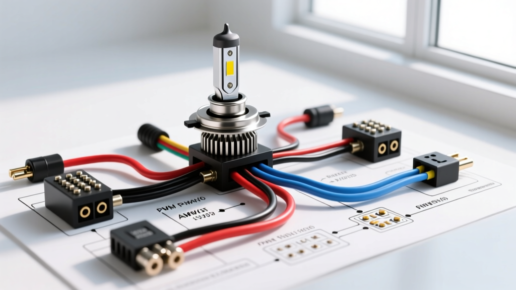
Why Factory Headlight Harnesses Fail During Upgrades
Upgrading from standard halogen sealed beams or H4 bulbs to high-output LED or HID lighting is one of the most effective safety modifications you can perform on a classic car, truck, or Jeep. However, simply plugging aftermarket LEDs into a factory headlight connector often results in severe voltage drop, dim output, flickering, or even catastrophic damage to the vehicle's Totally Integrated Power Module (TIPM) or Body Control Module (BCM). Factory wiring was engineered for the specific thermal and electrical resistance of 55W/65W halogen filaments, not the complex drivers and low-draw diodes of modern LEDs.
When you attempt to pull high-amperage startup loads (common with HIDs) or push continuous current through 30-year-old degraded copper, the factory headlight switch becomes a severe bottleneck. To bypass this, automotive electricians rely on a dedicated relay harness. By referencing a comprehensive car light wiring diagram designed for relay integration, you route heavy current directly from the battery to the headlights, using the factory headlight switch merely as a low-amperage trigger signal.
The H4 Relay Harness Car Light Wiring Diagram Explained
The standard dual-headlight relay upgrade utilizes a Bosch-style SPST (Single Pole, Single Throw) 12V 40A relay. This setup isolates the high-current lighting circuit from the vehicle's sensitive factory control modules. Below is the functional logic of the wiring diagram for a driver-side and passenger-side H4 LED upgrade.
Bosch-Style Relay Pinout Reference
Understanding the relay pinout is critical before making any crimps. Standard automotive relays follow the DIN 72552 numbering convention. For lighting upgrades, we utilize the 4-pin configuration, ignoring Pin 87a (Normally Closed).
| Relay Pin | Function | Wire Color (Standard) | Connection Point |
|---|---|---|---|
| Pin 30 | Common / Power In | 10 AWG Red | Direct to Battery Positive (+) via inline MAXI fuse |
| Pin 87 | Normally Open / Power Out | 14 AWG Red | Split to Driver & Passenger H4 Positive Terminals |
| Pin 85 | Coil Ground | 16 AWG Black | Chassis Ground or Battery Negative (-) |
| Pin 86 | Coil Trigger / Switch | 16 AWG Blue | Spliced into Factory H4 Low-Beam Positive Wire |
Wire Gauge and Connector Specifications
According to SAE J1128 standards for low-tension primary cable, selecting the correct AWG (American Wire Gauge) is vital to prevent voltage drop and insulation melting. Furthermore, using the correct weather-sealed connectors ensures the modification survives harsh engine bay environments.
| Circuit Segment | Recommended AWG | Strand Count | Connector Type | Insulation Method |
|---|---|---|---|---|
| Battery to Relay (Pin 30) | 10 AWG | 19 / 0.032" | Ring Terminal (3/8") | Dual-Wall Adhesive Heat Shrink |
| Relay to Headlights (Pin 87) | 14 AWG | 19 / 0.025" | H4 Ceramic Pigtail | Split-Loom & Tesa Fleece Tape |
| Relay Coil Trigger (Pin 86) | 16 AWG | 19 / 0.020" | Metri-Pack 280 / Posi-Tap | Adhesive Heat Shrink |
| Halo Ring / DRL Feed | 18 AWG | 16 / 0.016" | Weather-Pack 2-Way | Tesa 51036 PET Tape |
Step-by-Step Installation and Routing Execution
Executing this car light wiring diagram requires precision and the correct tooling. Do not use generic pliers to crimp weather-sealed terminals; use a dedicated Delphi Weather-Pack or Metri-Pack ratcheting crimper to ensure the wire core and insulation tabs are secured properly.
- Fuse Placement: Install a 20A MAXI fuse holder on the 10 AWG red wire within 6 inches of the battery positive terminal. This protects the entire harness in the event of a short to ground.
- Relay Mounting: Mount the 40A relay to the inner fender well or radiator support using a self-tapping stainless steel screw. Ensure the relay bracket is grounded to bare metal. Apply dielectric grease to the relay spades before inserting the connector block to prevent galvanic corrosion.
- Trigger Wire Splicing: Locate the factory H4 connector behind the headlight. Identify the low-beam positive wire (often Green/White or Red/Yellow depending on the manufacturer). Use a Posi-Tap connector or strip the insulation, solder the 16 AWG trigger wire, and seal with dual-wall adhesive heat shrink. Never use Scotch-Loks, as they allow moisture ingress and cause high-resistance failures.
- Grounding the Headlights: Factory H4 grounds are often insufficient for aftermarket setups. Run a dedicated 14 AWG ground wire from the negative terminal of each new H4 ceramic pigtail directly to a clean, bare-metal chassis ground point. Sand away paint and primer, apply a small amount of zinc-rich cold galvanizing compound to prevent rust, and torque the ground bolt to 10-15 ft-lbs.
- Loom and Routing: Bundle the 14 AWG output wires using corrugated split-loom tubing. Wrap the loom in Tesa 51036 PET fleece tape to eliminate rattling and provide high-temperature abrasion resistance. Route the harness away from exhaust manifolds, steering shafts, and belt drives.
Overcoming PWM and CANBUS Flicker Issues
Modern vehicles (particularly 2007+ Jeep Wranglers, Dodge Rams, and newer European platforms) do not send a steady 12V DC signal to the headlights. Instead, the TIPM or BCM uses Pulse Width Modulation (PWM) to rapidly cycle the voltage on and off. This is done to monitor bulb health and dim the lights for Daytime Running Light (DRL) modes. While halogens have enough thermal mass to ignore this rapid cycling, LED drivers interpret PWM as a command to flicker or strobe.
If your car light wiring diagram application involves a PWM-equipped vehicle, you must install an inline PWM decoder or anti-flicker capacitor module between the factory trigger wire and Pin 86 of the relay. A standard 4700µF 25V electrolytic capacitor wired in parallel with the trigger circuit will absorb the PWM pulses and release a steady 12V signal to the relay coil. Alternatively, plug-and-play CANBUS resistor modules can be installed inline with the H4 pigtails to simulate the 55W electrical load of a halogen bulb, satisfying the BCM's bulb-out detection algorithms.
Troubleshooting Common Modification Failures
Even with a perfect diagram, real-world variables can cause issues. Use this decision tree to diagnose post-installation electrical faults. For further reading on advanced relay logic and voltage drop calculations, consult the technical archives at Daniel Stern Lighting or review installation schematics from Painless Performance.
| Symptom | Probable Cause | Diagnostic Fix |
|---|---|---|
| LEDs flicker rapidly when engine is running | PWM signal from TIPM/BCM reaching the LED driver. | Install a PWM decoder/capacitor on the trigger wire or inline CANBUS module. |
| Relay clicks rapidly but lights do not turn on | Severe voltage drop on the trigger circuit or inadequate relay coil ground. | Measure voltage at Pin 86 during cranking. Clean chassis ground for Pin 85. |
| Headlights stay on after turning the switch off | Backfeeding from a shared DRL circuit or incorrect diode orientation. | Install a 1N5408 blocking diode on the trigger wire to enforce one-way current flow. |
| One headlight is dimmer than the other | High resistance on the passenger side ground or undersized wire gauge. | Perform a voltage drop test across the ground wire. Upgrade to 12 AWG if necessary. |
| Blown MAXI fuse upon initial power-up | Pinched 10 AWG main power wire shorting to chassis, or reversed H4 pigtail. | Inspect routing for sharp metal edges. Verify H4 pin orientation (Ground, Low, High). |
Final Inspection and Torque Checks
Before closing the hood, perform a final continuity check. Turn on the headlights and use a digital multimeter to measure the voltage directly at the H4 ceramic connector pins. You should read no less than 13.8V with the engine idling (alternator charging). If the voltage reads below 13.2V, you have excessive resistance in the 14 AWG output circuit or the battery-to-relay feed. Finally, verify that all battery terminal clamps are tightened to the manufacturer's specification (typically 7-10 Nm) and coated with a thin layer of dielectric grease to prevent acid corrosion.