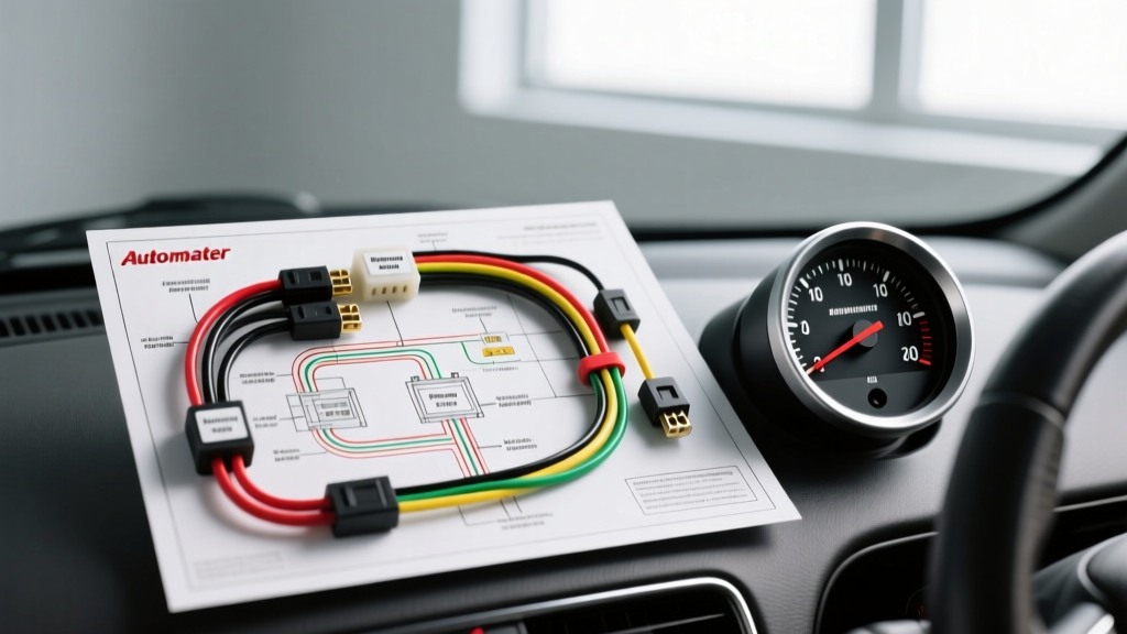
Introduction to AutoMeter Tachometer Wiring Fundamentals
Installing an aftermarket tachometer is a rite of passage for automotive enthusiasts, but interpreting a wiring diagram autometer tach schematic can feel overwhelming for beginners. Unlike simple accessory lights, a tachometer requires a precise, noise-free signal to accurately translate engine RPM into needle movement. A flawed installation will result in a dead gauge, erratic needle bounce, or inaccurate readings that can lead to missed shift points and engine damage.
This beginner-friendly guide breaks down the standard AutoMeter 4-wire harness, demystifies the various ignition signal sources, and provides actionable, expert-level routing and grounding techniques. Whether you are working on a classic carbureted V8 with a points distributor or a modern fuel-injected engine with Coil-on-Plug (COP) ignition, understanding the underlying electrical principles is critical. According to AutoMeter's official installation guidelines, the vast majority of warranty returns for 'defective' gauges are actually the result of improper signal wiring or poor grounding practices.
Understanding the Standard AutoMeter 4-Wire Pinout
Most standard AutoMeter tachometers (including the Z-Series, Ultra-Lite, and Phantom lines) utilize a standardized 4-wire harness. While the physical connector may vary, the color-coding remains consistent across the brand's ecosystem. The wire gauge utilized in the factory harness is typically 18 AWG, which is more than sufficient for the low-current draw of the gauge's stepper motor or air-core movement and LED lighting circuits.
| Wire Color | Function | AWG Size | Connection Point & Notes |
|---|---|---|---|
| Red | +12V Switched Power | 18 AWG | Fuse box ignition/accessory circuit. Must read 0V when key is off to prevent battery drain. |
| Black | Chassis Ground | 18 AWG | Clean, bare metal on the chassis or firewall. Do NOT ground to the engine block or intake manifold. |
| Green | Tachometer Signal | 18 AWG | Coil negative, distributor tach terminal, or ECU tach output. (See Signal Source Matrix below). |
| White | +12V Lighting/Dimmer | 18 AWG | Headlight dimmer circuit or dash illumination wire. Caps off if OEM dimming is not required. |
The Importance of the White Dimmer Wire
Beginners often mistakenly wire the white wire to a constant 12V source or leave it disconnected. If your gauge features incandescent perimeter lighting, the white wire controls the brightness. For modern AutoMeter gauges with Pro-Control or dimmable LEDs, wiring the white lead to the vehicle's headlight switch dimmer circuit allows the gauge to dim automatically when you turn on your headlights, preventing night-time glare. If your vehicle uses a PWM (Pulse Width Modulated) dimmer circuit (common in 2005+ GM and Chrysler vehicles), you must use an AutoMeter 2068 Dimmer Control Module, as standard LED gauges will strobe violently when connected directly to a PWM signal.
Identifying Your Tachometer Signal Source (The Green Wire)
The green wire is where 90% of installation errors occur. The tachometer expects a specific type of voltage pulse to calculate RPM. Different ignition systems generate entirely different signal profiles. Wiring a standard tach directly to a modern 5V logic signal without an adapter will result in a dead gauge, while wiring it to a high-voltage inductive spike without internal clamping can fry the gauge's microprocessor.
1. Points, Condenser, and GM HEI Distributors
In traditional points or GM HEI (High Energy Ignition) systems, the tach signal is derived from the negative terminal of the ignition coil. When the points or HEI module close the circuit, the coil negative drops to near 0V. When the circuit opens to fire the spark plug, the coil negative experiences a massive inductive flyback voltage spike (often exceeding 400V) before settling back to 12V. AutoMeter tachometers feature internal clamping diodes designed to safely read this harsh 12V square wave/inductive spike and filter out the high-voltage noise.
2. Ford TFI and Early EFI Systems
Early fuel-injected vehicles and Ford TFI (Thick Film Integrated) distributors usually feature a dedicated tach output terminal on the distributor or a specific pin on the ECU. These typically output a clean 12V square wave. The green wire can be connected directly to this source without an adapter.
3. Modern Coil-on-Plug (COP) and LS Engines
Modern engines like the GM LS series, Ford Coyote, and Chrysler HEMI do not have a single ignition coil. Instead, they use individual coils mounted directly on the spark plugs, fired sequentially by the PCM (Powertrain Control Module). You cannot tap into a single coil negative to read overall engine RPM, as it will only read the RPM of that specific cylinder (resulting in a tach reading that is a fraction of the actual RPM). Furthermore, the PCM logic drivers operate on 5V or 3.3V square waves, which the standard AutoMeter green wire cannot read natively.
To resolve this, you must use a dedicated PCM tach output pin and an adapter. As noted in the Haynes Automotive Wiring Manual, tapping into modern CAN-bus or low-voltage logic circuits requires specialized signal conditioning to prevent back-feeding voltage into the ECU and causing catastrophic misfires.
Signal Source & Adapter Matrix
Use this reference chart to determine if your specific engine requires an AutoMeter Tach Adapter to translate the signal for the green wire.
| Ignition System | Signal Source | Signal Type | Adapter Required? |
|---|---|---|---|
| Points / Condenser | Coil Negative (-) | Inductive Spike | No |
| GM HEI Distributor | TACH Terminal | 12V Square Wave | No |
| GM LS (1997-2013) | PCM Pin 10 (X) | 5V Square Wave | Yes (AutoMeter 9117) |
| Ford Coyote / Modular | PCM Tach Output | 5V Logic / Pull-up | Yes (AutoMeter 9120) |
| Chrysler HEMI (MDS) | PCM Tach Pin | 5V Pull-down | Yes (AutoMeter 9119) |
| Aftermarket CDI (MSD 6AL) | CDI Tach Output | 12V Square Wave | No (Use CDI white wire) |
Step-by-Step Execution & Best Practices
- Establish a Star Ground: Following SAE J1128 standards for low-tension primary wiring and grounding, never ground your tachometer to the engine block, cylinder head, or intake manifold. The alternator and ignition system dump massive amounts of electromagnetic interference (EMI) and AC ripple into the engine block. Ground the black wire to a clean, unpainted spot on the steel chassis or directly to the battery negative terminal to ensure a clean signal reference.
- Route the Harness Safely: Keep the green signal wire away from high-tension spark plug wires, alternator power cables, and the steering column. If you must cross a high-voltage wire, do so at a strict 90-degree angle to minimize inductive cross-talk.
- Make Secure Connections: Avoid 'scotch locks' or piercing connectors for the green signal wire. These introduce resistance, cause voltage drop, and allow moisture intrusion which will ruin a 5V PCM signal. Use a proper solder-and-heat-shrink method or a high-quality crimp terminal at the fuse box and ECU breakout.
- Set the Cylinder Switch: Before powering on the vehicle, flip the micro-switch on the back of the AutoMeter tach to match your engine's cylinder count (4, 6, or 8). Setting an 8-cyl switch on a 4-cyl engine will cause the gauge to read exactly half of the actual RPM.
Common Troubleshooting & Real-World Fixes
- Symptom: Needle Bounces Erratically at Idle.
Cause: Alternator whine or ignition noise interfering with the signal.
Fix: Check your ground. Use a digital multimeter set to AC Volts. Measure between the tachometer's black ground wire and the battery negative post. If you read more than 0.1V AC, your ground is contaminated by engine noise. Relocate the ground to the chassis. - Symptom: Tach Reads Exactly Half RPM.
Cause: Incorrect cylinder switch setting, or the signal is being pulled from a single coil pack on a 'wasted spark' system instead of the main ECU tach driver.
Fix: Verify the rear switch setting. If using a wasted spark system (like GM LQ4/LQ9), ensure you are using the correct PCM tach adapter to combine the signals. - Symptom: Gauge Lights Up But Needle Stays at Zero.
Cause: No signal reaching the green wire, or a 5V logic signal is being fed to a gauge expecting a 12V inductive spike.
Fix: Verify the signal source. If you are on a modern LS or Coyote engine, ensure the appropriate pull-up/pull-down adapter (e.g., 9117 or 9120) is installed between the PCM and the green wire. - Symptom: Needle Pegs at Maximum RPM Instantly.
Cause: The green signal wire is shorted to ground, or the gauge is set to 4-cyl while connected to an 8-cyl inductive source.
Fix: Inspect the green wire routing for pinched insulation touching the chassis. Verify cylinder selector switch.
By respecting the underlying electrical architecture of your specific ignition system and adhering to strict grounding protocols, your AutoMeter tachometer will provide years of accurate, flutter-free RPM data. Always consult your vehicle's specific factory service manual for exact ECU pinout locations before tapping into modern PCM circuits.