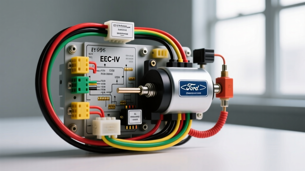
1995 Ford F-150 EEC-IV Fuel Delivery Architecture
The 1995 model year represents a critical era in Ford truck engineering. Unlike the 1996 models that transitioned to OBD-II and the EEC-V system, the 1995 Ford F-150 relies on the legendary EEC-IV (Electronic Engine Control IV) Powertrain Control Module (PCM). When analyzing the 1995 Ford F150 fuel pump wiring diagram, technicians must understand that this is not a simple switched-power circuit. It is a logic-driven safety system integrated with the Profile Ignition Pickup (PIP) signal and the Fuel Pump Monitor (FPM) circuit.
Whether you are troubleshooting a 4.9L inline-six, a 5.0L Windsor V8, or a 5.8L V8, the fundamental fuel pump relay architecture remains consistent. The circuit utilizes an under-hood power distribution relay, a cabin-mounted inertia shutoff switch, and a rear-chassis ground. This advanced technical deep dive will dissect the OEM wire color codes, AWG specifications, PCM pinout logic, and real-world failure modes that plague the 1995 F-150 platform.
Core Wiring Architecture & OEM Color Codes
Accurate diagnostics require a verified baseline of the factory harness. The fuel pump circuit is divided into three primary segments: the high-amperage power feed, the PCM logic control, and the safety interrupt loop. Below is the definitive specification chart for the 1995 F-150 fuel pump harness.
| Circuit Function | OEM Wire Color | AWG Size | Connector / Pin Location | Routing Path & Notes |
|---|---|---|---|---|
| Relay Constant Battery Feed | Yellow (or Black/Yellow) | 12 AWG | Relay Socket Pin 30 | Fusible link at starter relay to under-hood distribution box. Handles 20A+ continuous. |
| Relay Output to Inertia Switch | Pink/Black | 14 AWG | Relay Socket Pin 87 to C403 | Routes through firewall grommet to passenger cabin. Subject to chafing near kick panel. |
| Relay Coil Ignition Feed | Red/Light Green | 16 AWG | Relay Socket Pin 86 | Hot in RUN and START positions via ignition switch. |
| PCM Relay Ground Control | White (or Pink/Black) | 18 AWG | Relay Socket Pin 85 to PCM Pin 22 | EEC-IV internal transistor pulls this to ground to energize the relay coil. |
| Inertia Switch to Fuel Pump | Pink/Black | 14 AWG | C403 to Tank C450 | Runs along the interior floor pan, exits near the rear crossmember to the fuel tank. |
| Fuel Pump Ground | Black | 14 AWG | Tank C450 to Ground G400 | Attaches to the rear frame rail. Highly susceptible to corrosion and road debris damage. |
The Inertia Fuel Shutoff Switch (C403)
Located behind the passenger-side kick panel or under the right side of the dashboard, the inertia switch is a mechanical safety device designed to sever the power feed to the fuel pump in the event of a collision. The 1995 F-150 uses a two-pin connector (C403). If the vehicle experiences a sudden deceleration or impact (even hitting a severe pothole), the internal pendulum trips, breaking the Pink/Black 14 AWG circuit. Resetting requires pressing the plunger on top of the switch until it clicks.
EEC-IV PCM Logic: The PIP Signal & 2-Second Prime
A common diagnostic mistake among novice technicians is assuming the fuel pump relay is energized whenever the key is in the 'ON' position. According to Helm Incorporated Ford Service Manuals, the EEC-IV PCM employs a specific safety logic sequence:
- KOEO Prime: When the ignition is turned to RUN (Key On, Engine Off), the PCM grounds Pin 22 for exactly 2 seconds. This primes the fuel rails to approximately 35-45 PSI for starting.
- PIP Signal Dependency: After the 2-second prime, the PCM will only keep the fuel pump relay grounded if it receives a continuous Profile Ignition Pickup (PIP) signal from the distributor stator. The PIP signal confirms the engine is mechanically rotating.
- Safety Shutoff: If the engine stalls or is involved in an accident where the crankshaft stops turning, the PIP signal ceases. The PCM instantly opens the ground circuit at Pin 22, de-energizing the relay and killing the fuel pump to prevent post-crash fuel spraying.
Fuel Pump Monitor (FPM) Circuit Diagnostics
The 1995 EEC-IV system features a Fuel Pump Monitor circuit. The PCM monitors the voltage on the output side of the fuel pump relay. If the PCM commands the relay ON (grounds Pin 22) but detects zero voltage on the FPM input, it deduces that the inertia switch has tripped or the relay contacts have failed. This allows the PCM to disable the fuel injectors, preventing a flooded engine condition, and may trigger a specific continuous memory code.
Advanced Diagnostic Decision Tree
When utilizing a 1995 Ford F150 fuel pump wiring diagram for troubleshooting, follow this symptom-based decision tree to isolate electrical faults without unnecessarily dropping the fuel tank.
Symptom: Fuel Pump Runs Continuously with Key ON (Engine Off)
- Step 1: Turn the ignition OFF and disconnect the EEC-IV 60-pin PCM connector.
- Step 2: Turn the ignition back to RUN.
- Step 3 (Branch A): If the fuel pump stops running, the PCM internal driver transistor has shorted to ground. Fix: Replace or rebuild the EEC-IV PCM.
- Step 4 (Branch B): If the fuel pump continues to run, the under-hood fuel pump relay contacts are physically welded together due to high-amperage arcing. Fix: Replace the ISO mini relay and inspect the 12 AWG Yellow feed wire for heat damage.
Symptom: No Fuel Pump Prime, but Injectors Pulse
- Step 1: Check for 12V at the relay socket Pin 30 (Yellow wire) and Pin 86 (Red/Lt Green wire) with the key ON.
- Step 2: Use a test light between the battery positive terminal and relay socket Pin 85 (White wire).
- Step 3: Turn the key to RUN. The test light should illuminate for exactly 2 seconds.
- Step 4 (Branch A): If the light does NOT illuminate, check for an open circuit in the White 18 AWG wire between the relay and PCM Pin 22.
- Step 5 (Branch B): If the light DOES illuminate for 2 seconds, the PCM logic is functioning. The fault lies downstream. Check the inertia switch for continuity and inspect Ground G400.
Voltage Drop Testing & Ground G400 Restoration
Replacing a fuel pump without verifying the harness integrity is a leading cause of repeat failures. The 1995 F-150 fuel pump draws between 8 to 12 amps under normal operating pressure. A degraded ground or corroded connector will cause the pump to pull higher amperage, overheat, and fail prematurely. Adhering to SAE J1113 Standards for automotive electrical testing requires strict voltage drop limits.
- Power Side Voltage Drop: Connect your Digital Multimeter (DMM) positive lead to the battery positive post and the negative lead to the Pink/Black wire at the fuel tank connector (C450). Turn the key to RUN (or back-probe the relay while running). The voltage drop must be less than 0.5V. A reading of 1.2V indicates severe corrosion in the inertia switch connector or the firewall bulkhead.
- Ground Side Voltage Drop: Connect the DMM negative lead to the battery negative post and the positive lead to the Black ground wire at the fuel pump connector. The drop must be less than 0.1V.
Ground G400 Restoration: The Black 14 AWG ground wire terminates at Ground G400, located on the rear frame rail near the spare tire crossmember. This location is highly exposed to road salt and moisture. To properly restore this ground, unbolt the terminal, wire-brush the frame contact pad down to bare metal, apply a thin layer of dielectric grease to prevent future oxidation, and torque the retaining bolt to 106 lb-in (12 Nm).
Common Harness Chafing Points & Real-World Failure Modes
Beyond the relay and the PCM, the physical routing of the 1995 F-150 harness presents specific vulnerability points that master technicians must inspect:
- The Parking Brake Cable Intersection: As the Pink/Black 14 AWG wire routes along the interior floor pan towards the rear, it passes dangerously close to the parking brake cable tensioner. Over decades of use, cable vibration can wear through the factory loom and short the fuel pump circuit to the chassis, instantly blowing the 20A fuse link at the starter relay.
- The Frame Rail Saddle: Where the harness drops from the cabin to the fuel tank sender unit, it rests against the top of the steel frame rail. Rust jacking and debris accumulation frequently compromise the split-loom tubing, exposing the Pink/Black and Black wires to the elements.
- Sender Unit Flange Corrosion: The connection at the top of the fuel tank (C450) is prone to capillary action drawing moisture into the connector pins. If you find green verdigris on the terminals, do not simply clean it. The pin tension is likely compromised. Splice in a new Motorcraft OEM pigtail using sealed adhesive-lined heat shrink to ensure a weather-tight repair.
By treating the 1995 Ford F150 fuel pump wiring diagram not just as a map of wires, but as a logic-controlled safety network, you can accurately diagnose EEC-IV faults, eliminate voltage drop issues, and ensure reliable fuel delivery for the lifespan of the vehicle.