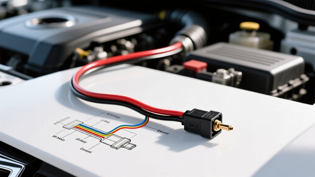
Understanding the GM LS 2-Pin ECT Sensor Circuit
When performing an engine swap or upgrading to a standalone electronic fuel injection (EFI) system, interpreting the temperature sensor wiring diagram correctly is critical for engine survival. The Engine Coolant Temperature (ECT) sensor dictates cold-start fuel enrichment, closed-loop transition points, ignition timing compensation, and electric cooling fan activation. A poorly wired ECT circuit will result in erratic idle quality, dangerous lean conditions on cold starts, or overheating due to delayed fan engagement.
The GM LS-series engine family utilizes a 2-pin Negative Temperature Coefficient (NTC) thermistor for coolant temperature monitoring. Unlike older 1-pin sensors that relied on the engine block for a chassis ground, the modern 2-pin Delphi sensor utilizes a dedicated analog ground circuit back to the Powertrain Control Module (PCM) or standalone ECU. This isolated ground design prevents 'ground offset' errors caused by voltage differentials between the engine block, chassis, and battery negative terminal.
Decoding the Temperature Sensor Wiring Diagram
Whether you are wiring a factory GM 59-pin/88-pin PCM or an aftermarket ECU like the Holley Terminator X, the fundamental circuit topology remains identical. The ECU provides a 5-volt reference signal through an internal pull-up resistor to the sensor. The sensor acts as a variable resistor to ground. As coolant temperature increases, the thermistor's resistance decreases, allowing more current to flow and dropping the voltage on the signal wire. The ECU reads this voltage drop (typically ranging from 4.8V at -40°F to 0.1V at 284°F) and cross-references it with an internal calibration table.
According to Holley EFI technical documentation, the signal wire must be routed away from high-voltage ignition components to prevent Electromagnetic Interference (EMI). Because the ECT signal is a low-voltage, high-impedance analog circuit, it is highly susceptible to noise induction from ignition coils and alternator stator wires.
Pinout and Wire Specification Chart
When fabricating a custom harness or extending a factory pigtail, adhering to SAE J1128 standards for under-hood wiring is mandatory. Standard PVC wire will melt and become brittle; you must use Cross-Linked (TXL or GXL) wire.
| Sensor Pin | Function | Wire Color (Standard) | Wire Gauge & Type | ECU Termination Point |
|---|---|---|---|---|
| Pin A (1) | ECT Signal | Yellow or Dark Green | 18 AWG TXL Shielded | ECU Analog Input (e.g., Pin 16) |
| Pin B (2) | Sensor Low / Ground | Black | 18 AWG TXL Shielded | ECU Analog Ground (e.g., Pin 79) |
Step-by-Step Installation & Harness Fabrication
Proper installation goes beyond simply plugging in a connector. The harsh environment of the engine bay demands meticulous attention to thread sealing, crimping profiles, and shielding.
Step 1: Sensor Thread Preparation and Torque
The factory LS water pump and cylinder heads utilize various thread pitches depending on the generation (Gen III vs. Gen IV). If you are using an aftermarket adapter fitting (such as a 3/8" NPT to M12x1.5 brass adapter), ensure the adapter is sealed with liquid PTFE thread sealant (e.g., Loctite 565 or Permatex 56521). Never use Teflon tape. Teflon tape can shred, travel through the cooling system, and clog heater cores or radiator tubes. Furthermore, if tape wraps around the sensor threads, it can act as an electrical insulator, though the 2-pin sensor is internally grounded, stray tape can interfere with adjacent block-grounded sensors.
Torque the sensor or adapter to 15 lb-ft. Over-torquing can crack the brass housing or strip the aluminum water pump threads, leading to catastrophic coolant loss under pressure.
Step 2: Crimping the Delphi Metri-Pack 280 Connector
The GM LS 2-pin ECT sensor uses a Delphi Metri-Pack 280 series weather-sealed connector (ACDelco pigtail part #88862584). The terminals feature an 'open barrel' crimp design. You cannot use standard closed-barrel electrical crimpers. You must use a ratcheting open-barrel crimper (such as the Delphi 12094428 or an equivalent Titan/Waytek tool) to form the precise 'W' or 'B' crimp profile on the wire strands and the insulation grip.
- Strip exactly 4mm of insulation from the 18 AWG TXL wire.
- Insert the wire into the terminal barrel. The wire strands should be flush with the front edge of the conductor crimp wings.
- Crimp the conductor wings first, ensuring a gas-tight mechanical bond.
- Crimp the insulation support wings over the wire jacket to provide strain relief.
- Slide the yellow silicone weather seal over the wire before crimping, and seat it into the back of the connector housing until it clicks.
Step 3: Routing and EMI Shielding
Because the temperature sensor wiring diagram deals with a 0-5V analog signal, routing is critical. Route the ECT harness at least 4 inches away from ignition coil power wires, fuel injector harnesses, and the alternator output cable. If you must cross a high-voltage wire, do so at a strict 90-degree angle to minimize inductive coupling. For ultimate noise rejection, use a shielded twisted-pair cable for the ECT circuit, grounding the shield drain wire only at the ECU end to prevent ground loops.
Bench Testing the NTC Thermistor Before Installation
Before sealing the cooling system and firing the engine, verify the sensor's resistance curve using a digital multimeter (DMM). Submerge the sensor tip in a pot of heated water alongside a calibrated thermometer. According to Delphi Technologies specifications, a standard GM 2-pin NTC thermistor should exhibit the following approximate resistance values:
- 68°F (20°C): 2,500 - 3,000 Ohms
- 122°F (50°C): 800 - 950 Ohms
- 176°F (80°C): 300 - 350 Ohms
- 212°F (100°C): 175 - 200 Ohms
If your DMM reads 'OL' (Open Loop) or 0.00 Ohms (Short), the internal thermistor bead has failed and the sensor must be replaced before proceeding.
Real-World Troubleshooting: Ground Offsets and EMI
Even with a perfect temperature sensor wiring diagram, real-world variables can corrupt the signal. The most common issue in EFI swaps is the 'Ground Offset'. This occurs when the ECU's analog ground reference is slightly higher than the engine block's ground. For example, if the ECU ground is at 0.05V due to a poor battery ground strap, the ECU will read the ECT signal 0.05V higher than reality. At operating temperature, a 0.05V offset can trick the ECU into reading the engine as 30°F cooler than it actually is, causing the fans to never engage and the engine to overheat.
Diagnostic Fix: Perform a voltage drop test. With the ignition ON (engine OFF), back-probe the sensor ground wire at the connector and measure the DC voltage between the sensor ground pin and the negative battery terminal. The reading must be less than 0.02V. If it is higher, run a dedicated 14 AWG ground strap from the ECU analog ground pin directly to the engine block, bypassing the chassis entirely.
Another frequent failure mode is EMI noise from MSD or aftermarket CDI ignition boxes. If your ECT reading fluctuates wildly on the dashboard (e.g., jumping from 190°F to 240°F and back in milliseconds), your signal wire is acting as an antenna. Installing a 0.1µF ceramic capacitor between the signal wire and the analog ground wire at the ECU connector will filter out high-frequency ignition noise without affecting the slow-moving DC voltage of the thermistor.