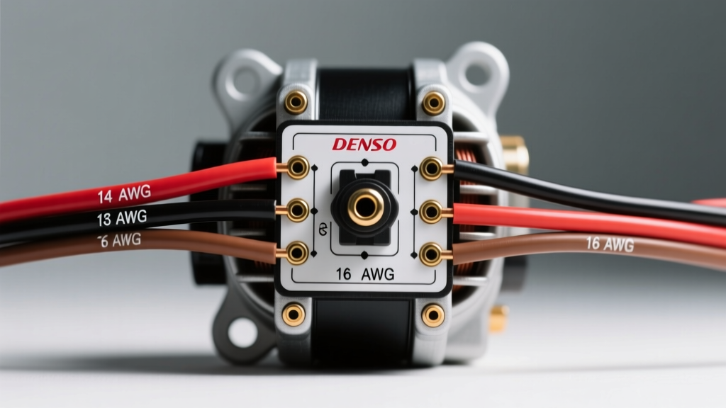
Introduction to Denso 3-Pin Alternator Regulators
Denso alternators are the premier OEM charging solution for a vast majority of Asian and domestic vehicles, prominently featured in Toyota, Lexus, Honda, Subaru, and General Motors applications. The hallmark of the classic Denso charging system is the 3-pin voltage regulator plug. Understanding the Denso alternator 3 pin plug wiring diagram is critical for diagnosing charging system faults, performing engine swaps, or upgrading to high-output aftermarket units.
Unlike older single-wire or two-wire externally regulated alternators, the Denso 3-pin system utilizes an internal voltage regulator that requires three distinct signal inputs to manage stator output accurately. These terminals—designated as S (Sense), L (Lamp/LIN), and IG (Ignition)—work in concert to maintain optimal system voltage, manage dashboard indicator lights, and communicate with the vehicle's Engine Control Module (ECM). This technical reference provides exact pinout configurations, wire gauge requirements, and advanced diagnostic procedures for both legacy SC1 and modern SC2 (LIN-bus) Denso alternators.
Denso Alternator 3 Pin Plug Wiring Diagram Breakdown
The physical connector is typically a Yazaki 090 series or Sumitomo TS 0.64 unsealed or semi-sealed 3-way housing. Pin cavities are usually molded into the plastic connector housing. Below is the definitive specification chart for the 3-pin regulator plug.
| Pin Cavity | Terminal ID | Function | Typical OEM Wire Color | Min. AWG | Routing Destination |
|---|---|---|---|---|---|
| 1 | S (Sense) | Battery Voltage Feedback | White or Red | 14-16 AWG | Battery (+) Post or Main Fuse Block |
| 2 | L (Lamp / LIN) | Charge Indicator / ECU PWM | Yellow or Green | 18-20 AWG | Dashboard Lamp / ECM LIN Bus |
| 3 | IG (Ignition) | Regulator Wake-Up Signal | Black/White Tracer | 16-18 AWG | Ignition Switch (IG1 Circuit) |
Terminal Circuit Analysis and Routing Specifications
Terminal S (Sense): The Voltage Feedback Loop
The 'S' terminal is the most critical wire in the Denso alternator 3 pin plug wiring diagram. Its sole purpose is to monitor the actual voltage reaching the vehicle's main electrical distribution center or the battery positive post. The internal voltage regulator uses this feedback to adjust rotor field current.
Technical Warning: A common aftermarket wiring mistake is routing the 'S' wire directly to the alternator's B+ output stud. If this occurs, the regulator senses voltage at the alternator, ignoring the voltage drop across the main B+ charge cable. Under heavy electrical loads (e.g., cooling fans, headlights, audio amplifiers), the voltage drop across the B+ cable can exceed 0.5V. The alternator will overcompensate, pushing system voltage past 15.0V, which will boil lead-acid battery cells and potentially destroy sensitive ECM logic boards. The 'S' wire must always be routed independently to the battery or main fuse block junction.
Terminal L (Lamp / LIN Bus): Excitation and ECU Communication
The function of the 'L' terminal depends on the generation of the Denso alternator:
- Legacy SC1 Alternators (Pre-2005 approx.): The 'L' terminal connects to the dashboard charge indicator lamp. When the ignition is turned on, 12V flows through the incandescent bulb (typically 3W to 5W) into the 'L' terminal, providing the initial excitation current required to energize the rotor and initiate charging. Once the alternator begins producing current, the regulator grounds the 'L' terminal internally, equalizing voltage on both sides of the bulb and turning it off.
- Modern SC2 Alternators (LIN-Bus Equipped): In newer Toyota, Lexus, and GM applications, the 'L' terminal serves as a Local Interconnect Network (LIN) bus communication line. The ECM sends a 5V or 12V Pulse Width Modulation (PWM) square wave signal to the regulator. This allows the ECM to command specific voltage targets (e.g., dropping to 12.8V during deceleration fuel cut to reduce engine drag, or spiking to 14.8V during heavy battery recharge phases).
Terminal IG (Ignition): The Wake-Up Signal
The 'IG' terminal requires a switched 12V source, typically sourced from the ignition switch's IG1 circuit or a main EFI relay. This signal 'wakes up' the voltage regulator's internal logic board. If the 'IG' wire is mistakenly wired to a constant 12V battery source, the regulator will remain active when the vehicle is turned off, leading to a severe parasitic draw that will drain the battery overnight.
Wire Gauge (AWG) and Voltage Drop Standards
Adhering to SAE International Electrical Standards is mandatory when repairing or fabricating a Denso 3-pin harness. The 'S' (Sense) wire carries virtually zero amperage, but it is highly susceptible to electromagnetic interference (EMI) and voltage drop. According to Toyota Technical Information System (TIS) guidelines, the voltage drop on the 'S' sense circuit should not exceed 0.1V with the engine running and all accessories loaded.
When repairing broken wires in the harness, always use oxygen-free copper (OFC) wire. Use 14 AWG for the 'S' wire if the run exceeds 4 feet to minimize resistance. For the 'L' and 'IG' circuits, 18 AWG TXL or GXL cross-linked automotive wire is sufficient, provided the circuit is protected by a 5A or 10A inline fuse near the ignition switch source.
Connector Extraction and Terminal Crimping
The Denso 3-pin plug utilizes specific female terminals with silicone weather seals (on newer sealed variants) or standard unsealed friction locks. To extract a damaged terminal, you must use a precision terminal removal tool (such as a Lisle 47900 or equivalent Yazaki 090 extractor). Prying with a flathead screwdriver will permanently deform the plastic locking tang inside the connector housing, resulting in a loose connection and intermittent charging faults caused by engine bay vibrations.
When crimping new terminals, use a ratcheting micro-terminal crimping tool. Soldering is strictly prohibited on automotive alternator harnesses; solder wicks under the wire insulation and creates a rigid stress point that will inevitably snap under engine movement and thermal cycling.
Diagnostic Decision Tree: Real-World Failure Modes
Use this structured diagnostic approach when troubleshooting charging anomalies related to the 3-pin plug.
Symptom 1: Battery Overcharging (15.2V or Higher)
- Cause: High resistance or an open circuit on the 'S' (Sense) wire. The regulator reads 0V or artificially low voltage and maxes out the stator output.
- Test: Perform a voltage drop test. Place the positive multimeter probe on the battery positive post and the negative probe on the alternator B+ stud. If the voltage drop exceeds 0.5V under load, inspect the main B+ cable. Next, backprobe the 'S' terminal at the alternator plug and measure voltage to ground. It should read within 0.1V of the battery post voltage.
- Fix: Repair the 'S' wire or reroute it directly to the battery positive terminal with an inline 15A fuse.
Symptom 2: Alternator Not Charging Until Engine is Revved
- Cause: On legacy SC1 alternators, this indicates a blown dashboard charge indicator bulb or an open 'L' wire. Without the bulb, the rotor receives no initial excitation current at idle RPMs.
- Test: Turn the key to the 'ON' position (engine off). Verify the battery icon illuminates on the dash. If it does not, check the bulb and the 'L' wire continuity.
- Fix: Replace the incandescent dash bulb (do not use an LED replacement, as LEDs do not draw enough current to excite the rotor) or repair the 'L' circuit.
Symptom 3: Parasitic Battery Drain Overnight
- Cause: The 'IG' terminal is receiving constant 12V instead of switched ignition power, keeping the regulator logic board awake.
- Test: Connect an ammeter in series with the negative battery cable. Pull the 3-pin alternator plug. If the parasitic draw drops significantly, the alternator is the culprit. Backprobe the 'IG' wire with the key OFF; if it reads 12V, it is wired incorrectly.
- Fix: Reroute the 'IG' wire to a verified switched IG1 source, such as the wiper motor fuse or ignition coil fuse circuit.
Expert Insights on ECU Integration
For technicians working on late-model vehicles equipped with Denso LIN-bus alternators, replacing the OEM unit with a generic 'one-wire' or incorrectly wired aftermarket alternator will trigger a Check Engine Light (e.g., Toyota DTC P0620 - Generator Control Circuit Malfunction). The ECM expects a specific PWM duty cycle feedback signal on the 'L' terminal. If you are performing an engine swap (such as a 2JZ or LS swap into a chassis requiring CAN/LIN alternator data), you must retain the OEM Denso 3-pin alternator and wire the LIN bus directly to the corresponding ECM pin to maintain proper vehicle electrical architecture.
For comprehensive OEM wiring schematics and connector cavity views, always consult the Denso Aftermarket Alternator Technical Guide or factory service manuals before cutting or splicing any factory harness wires.