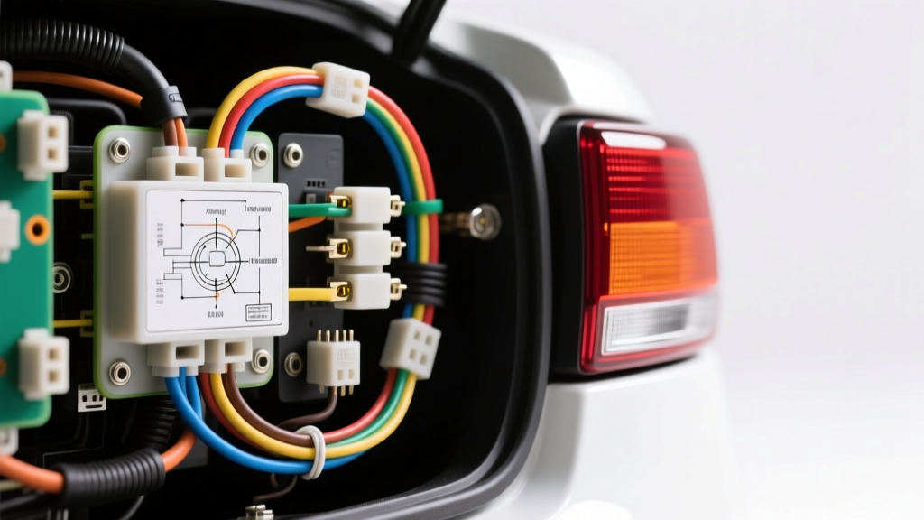
The Hidden Dangers of Misinterpreting a Tail Light Wiring Diagram
When consulting a tail light wiring diagram, many DIY mechanics and even seasoned technicians make assumptions based on legacy automotive electrical systems. Modern vehicles, however, utilize complex multiplexed networks, Pulse Width Modulation (PWM), and sensitive Body Control Modules (BCMs) to manage exterior lighting. Misinterpreting the schematic or ignoring safety protocols can result in catastrophic electrical failures, including fried MOSFETs, CAN-bus network crashes, or severe fire hazards. This guide outlines the most critical safety warnings and common mistakes associated with tail light circuit modifications, repairs, and trailer towing integrations.
Critical Safety Warnings Before You Splice
Before probing any wires or consulting your vehicle-specific schematic, adhere to these non-negotiable safety protocols to protect both yourself and the vehicle's sensitive electronics:
- Battery Isolation Protocol: Always disconnect the negative battery terminal first. On modern vehicles with SRS (airbag) components routed through the trunk or rear C-pillars, wait a minimum of 10 minutes after disconnection to allow the backup capacitors to discharge.
- Avoid Hot-Splicing: Never cut, strip, or splice wires while the circuit is energized. A momentary short to ground on a BCM-controlled circuit can instantly destroy the internal solid-state relay, requiring a $1,200+ module replacement and proprietary dealer programming.
- ESD Precautions: When handling LED control modules or smart junction blocks, use an anti-static wrist strap. Electrostatic discharge can silently corrupt the logic boards governing the rear lighting matrix.
- Proper Grounding Torque: When reattaching ground rings to the chassis, use a torque wrench. An M6 ground stud welded to the rear body pan typically requires 7 to 10 Nm (62-88 in-lbs). Overtorquing strips the weld nut; undertorquing creates high resistance and voltage drop.
Top 5 Tail Light Wiring Diagram Mistakes
1. Overloading the Body Control Module (BCM) MOSFETs
In vehicles manufactured after 2010, the BCM often drives the tail lights directly using internal Metal-Oxide-Semiconductor Field-Effect Transistors (MOSFETs) rather than external mechanical relays. A common mistake occurs when adding aftermarket LED light bars or auxiliary reverse lights directly to the factory tail light circuit. The BCM monitors current draw; if the added load exceeds the circuit's designed amperage (typically 5A to 10A per channel), the BCM will trigger a short-circuit protection lockout. Worse, tapping into a circuit meant for low-draw LEDs to power high-draw halogen off-road lights will melt the BCM traces. Always use a 12V automotive relay or a dedicated PWM-capable LED driver triggered by the factory wire.
2. Ignoring Pulse Width Modulation (PWM) on Euro Vehicles
Many European platforms (such as the VW MQB or BMW F/G chassis) use a single wire and bulb/LED array for both the running tail light and the brighter brake light. The BCM achieves this via PWM—rapidly pulsing the voltage. A low duty cycle (e.g., 20%) provides the dim tail light, while a 100% duty cycle provides the bright brake light. If you tap this wire to install a third brake light or a trailer module without a proper PWM decoder, the accessory will strobe violently or fail to illuminate. You must use an oscilloscope to verify PWM signals and install a dedicated PWM-to-DC signal converter.
3. Misunderstanding Combined vs. Separate Stop/Turn Circuits
US DOT regulations historically allowed combined stop/turn signals (3-wire systems: Left, Right, Ground), while ECE regulations mandate separate amber turn signals and red brake lights (4-wire or 5-wire systems). When installing a trailer hitch, tapping into a combined circuit to feed a separate-circuit trailer will cause the trailer brakes to pulse when turning, or the turn signals to illuminate the entire trailer side. Always verify if your vehicle requires a 3-to-2 wire tail light converter module with an internal isolation relay.
4. Using 'Scotch-Lok' T-Taps Instead of Automotive Connectors
T-taps and Scotch-Loks pierce the wire insulation to make contact. In the harsh, high-vibration, and moisture-prone environment of a vehicle's rear quarter panel or trunk, these connectors inevitably allow water ingress. This leads to galvanic corrosion, copper oxidation, and high-resistance voltage drops. The correct method is to strip the wire, use a proper crimp with a TE Automotive AMP seal, or solder and seal with dual-wall polyolefin heat shrink containing an inner adhesive layer. According to the Society of Automotive Engineers (SAE), proper crimping and sealing are mandatory for maintaining OEM-level circuit integrity.
5. Bypassing the Trailer Tow Isolation Module
Directly splicing a 4-way flat trailer connector into the rear tail light harness is a massive mistake on modern trucks and SUVs. Trailer wiring should be routed through an isolation module (often called a tow converter). This module draws power directly from the battery via a fused 12V feed (usually 12 AWG or 10 AWG) and uses the vehicle's tail light wires merely as low-current trigger signals. Bypassing this module forces the vehicle's thin 18 AWG tail light wires to carry the combined amperage of the truck and trailer lights, leading to melted harnesses and fire.
Standard Tail Light Wire Specifications & Color Codes
Wire colors vary heavily by manufacturer, but understanding standard AWG sizing and common color conventions helps when cross-referencing a generic tail light wiring diagram against a multimeter reading. Always verify with a digital multimeter (DMM) before cutting.
| Circuit Function | Typical US OEM Color | Typical Euro/DIN Color | Standard AWG / Metric | Max Continuous Ampacity |
|---|---|---|---|---|
| Running / Tail Light | Brown or Dark Green | Grey (Grau) or Brown | 18 AWG (0.8 mm²) | 7A - 10A |
| Stop / Brake Light | White or Light Green | Black/Red or Black/Yellow | 16 AWG (1.3 mm²) | 10A - 13A |
| Left Turn Signal | Yellow or Light Blue | Black/White | 18 AWG (0.8 mm²) | 7A - 10A |
| Right Turn Signal | Dark Green or Dark Blue | Black/Green | 18 AWG (0.8 mm²) | 7A - 10A |
| Chassis Ground | Black or Bare Copper | Brown (Braun) | 16 AWG (1.3 mm²) | Match Positive Feed |
Note: The National Highway Traffic Safety Administration (NHTSA) mandates specific photometric outputs for brake and tail lights; altering wire gauge too drastically or introducing high-resistance splices can cause voltage drop, resulting in illegal light output levels.
Proper Diagnostic Protocol for Tail Light Failures
When a tail light circuit fails, do not immediately assume a bad bulb or broken wire. Follow this systematic diagnostic tree to protect the vehicle's CAN-bus network:
- Scan for BCM Codes: Use an advanced bi-directional OBD2 scanner to check the BCM for 'Short to Ground', 'Short to Battery', or 'Open Circuit' codes on the specific lighting output.
- Perform a Voltage Drop Test: With the lights commanded ON, place your DMM in DC Volts. Put the positive probe on the battery negative terminal and the negative probe on the tail light ground wire. A reading above 0.1V indicates a corroded ground stud or pin.
- Check for Parasitic LIN-Bus Activity: On vehicles using Local Interconnect Network (LIN) bus for rear lighting, disconnect the tail light connector and measure resistance between the signal wire and ground. If it reads near zero ohms, the module has failed internally, not the wiring.
- Verify Connector Pin Tension: Use a pin drag-test tool. If the male blade slides into the female terminal without noticeable friction, the terminal is fatigued and will cause intermittent flickering under vibration. Replace the pigtail using OEM-crimped leads.
Authoritative References & Further Reading
For exact pinouts, connector cavity numbers, and torque specifications for your specific make and model, always consult factory service manuals (FSM) or verified aftermarket equivalents. The SEMA Garage provides excellent technical bulletins on aftermarket lighting integration and compliance with Federal Motor Vehicle Safety Standards (FMVSS 108). Never rely on unverified forum diagrams when modifying safety-critical lighting circuits.