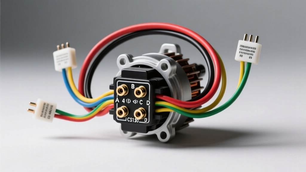
Introduction to the CS130 Generator System on the GMT400 Platform
The 1994 Chevrolet C/K 1500 represents a pivotal era in GM’s GMT400 truck lineage. By 1994, GM had fully transitioned away from the older, externally regulated SI10 alternators and the early internally regulated CS130 designs, settling on a refined 105-amp Delco CS130 generator for the majority of 5.0L (305ci) and 5.7L (350ci) V8 applications. Understanding the 1994 Chevy 1500 alternator wiring diagram requires more than just tracing a few cables; it demands a thorough comprehension of the integral voltage regulator logic, the specific 4-pin Packard/Delphi connector pinout, and the common degradation points inherent to 30-year-old engine bay harnesses.
Unlike modern LIN-bus controlled alternators, the 1994 CS130 relies on a parallel-circuit exciter setup and a dedicated remote voltage sense wire to maintain a target system voltage of 13.8V to 14.4V. In this advanced technical deep dive, we will dissect the OEM wiring schematic, detail the exact AWG specifications and wire color codes, and provide actionable diagnostic procedures for the most prevalent CS130 charging system failures.
1994 Chevy 1500 Alternator Wiring Diagram: The 4-Pin Connector
The heart of the CS130’s control system is the 4-pin oval connector located at the rear of the alternator casing, adjacent to the B+ output post. While the connector houses four terminals, only two or three are typically populated in a standard 1994 C/K 1500 application, depending on the RPO (Regular Production Option) codes and whether the truck is equipped with a digital instrument cluster or specific towing packages.
OEM Pinout Breakdown and Wire Color Codes
Below is the definitive reference table for the 1994 CS130 4-pin pigtail. Wire colors are based on the standard GM GMT400 factory service manual schematics for the C/K 1500 pickup.
| Terminal | Designation | OEM Wire Color | AWG Size | Destination / Function |
|---|---|---|---|---|
| L | Lamp / Exciter | Brown | 18 AWG | Instrument Cluster Charge Lamp & Ignition Switch (via 56Ω resistor) |
| F | Field | Gray | 18 AWG | PCM / Tachometer Filter (PWM duty cycle monitoring) |
| P | Phase | Purple | 18 AWG | Stator Tap (Often unpopulated on '94 base models; used for relays) |
| S | Sense | Red | 12 AWG | Battery Junction Block / Starter Solenoid (Direct Battery Voltage Read) |
Circuit Trace & Voltage Regulation Logic
To properly troubleshoot a no-charge or overcharge condition using the 1994 Chevy 1500 alternator wiring diagram, you must understand how the internal voltage regulator utilizes these four terminals to dictate rotor field strength.
Terminal L (Lamp/Exciter) Circuit
The L terminal serves a dual purpose. First, it provides the initial “exciter” current to the rotor windings to bootstrap the alternator’s magnetic field upon startup. When the ignition is turned to the RUN position, 12V flows from the ignition switch, through the instrument cluster charge indicator bulb, and down the Brown 18 AWG wire to the L terminal.
Critically, GM wired a 56-ohm, 1/2-watt resistor in parallel with the dashboard bulb. If the bulb burns out, the resistor ensures the alternator still receives the minimum 0.5A required to excite the field. Once the alternator begins generating its own AC voltage, the internal regulator rectifies a portion of it and feeds it back to the L terminal. This equalizes the voltage on both sides of the dashboard bulb, extinguishing the light. Diagnostic Tip: If you have swapped your dash cluster to LEDs without installing a load resistor, the CS130 will fail to excite, resulting in a dead battery.
Terminal S (Sense) Circuit
The S terminal is the most critical wire for maintaining stable system voltage. The Red 12 AWG wire routes directly from the alternator pigtail, through the engine bay harness, to the main battery junction block or the starter solenoid B+ post. This allows the internal regulator to “sense” the actual voltage at the battery, compensating for voltage drop across the 4 AWG main charging cable. If this Red sense wire is broken, corroded at the bulkhead, or incorrectly zip-tied to the alternator case, the regulator will sense voltage at the alternator output post rather than the battery. This causes the regulator to prematurely taper off field current, resulting in an undercharged battery (typically resting around 12.6V while the engine runs).
Terminal F (Field) & P (Phase) Terminals
The Gray F wire outputs a Pulse Width Modulated (PWM) signal representing the voltage regulator’s field duty cycle. On 1994 models equipped with the 5.7L TBI (Throttle Body Injection) or early Vortec prep packages, the PCM monitors this signal to adjust idle air control (IAC) steps when high electrical loads (like cooling fans or rear defrosters) engage. The Purple P wire taps into one of the stator windings, providing an AC signal that is half the system voltage. It is rarely used on the 1994 C/K 1500 but is sometimes utilized in aftermarket dual-battery isolator setups or PTO relay triggers.
Main Output (B+) and Grounding Specifications
The primary charging output exits the CS130 via the B+ stud on the rear housing. From the factory, this is secured with an M8 nut (torque spec: 95 in-lbs / 11 Nm) and routes a 4 AWG Red cable directly to the starter solenoid, where it joins the main battery cable.
While the CS130 relies on the aluminum alternator case mating to the cast-iron engine bracket for its ground path, 30 years of heat cycling, galvanic corrosion, and engine vibration severely compromise this connection. Advanced Fix: Always install a dedicated 8 AWG braided ground strap from one of the alternator case mounting ears directly to a clean, bare-metal point on the engine block or cylinder head. This eliminates ground-loop noise in the stereo system and ensures the voltage regulator has a flawless 0.00V reference point.
Common Failure Modes & Advanced Troubleshooting
When diagnosing a GMT400 charging system issue, rely on a digital multimeter (DMM) and an oscilloscope rather than guessing based on dashboard lights. Here are the most common failure modes specific to the 1994 CS130 wiring and hardware:
1. The Internal B+ Solder Joint Crack
The CS130 is notorious for running hot due to its internal fan design, which pulls air in from the rear and exhausts it radially. Over time, the heat causes the solder joint connecting the B+ copper post to the internal rectifier bridge to crack. Symptom: The alternator charges fine at idle but drops to 12.2V at highway RPMs, or the B+ post physically melts the rear plastic housing. Fix: Disassemble the rear cover and re-flow the B+ post solder joint with high-temp rosin-core solder, or upgrade to an AD244 alternator which uses a bolted-through B+ post.
2. Firewall Bulkhead Connector Degradation
The 1994 Chevy 1500 wiring harness passes through a massive multi-pin bulkhead connector on the firewall. The Red Sense (S) and Brown Exciter (L) wires pass through this junction. Moisture intrusion causes the copper terminals to oxidize, creating a high-resistance bottleneck. Test: Perform a voltage drop test across the firewall bulkhead on the Red Sense wire with the engine running and all accessories on. A voltage drop greater than 0.15V indicates bulkhead corrosion, requiring terminal extraction and dielectric grease application.
3. Diode Trio Thermal Failure
The CS130 utilizes a diode trio to rectify AC stator voltage into DC current specifically for the internal voltage regulator. If the diode trio fails open, the alternator will not self-excite, and the dash light will remain illuminated. Test: Use a DMM in diode-test mode across the trio heat sink tabs inside the rear housing. You should read 0.5V to 0.7V in one direction and OL (Open Loop) in the reverse. Any reading of 0.0V indicates a shorted diode.
Upgrading the 1994 C/K 1500 Charging System
For trucks equipped with high-draw accessories (off-road lighting, winches, or massive audio amplifiers), the 105A CS130 is inadequate. The most reliable OEM-style upgrade is swapping to the Delco AD244 (145A) or the DR44G (130A+). These later-generation alternators feature external cooling fans and vastly superior voltage regulator heat sinks. To execute this swap on a 1994 harness, you will need a 4-pin to 4-pin adapter pigtail (often sold as a CS-to-AD adapter), as the regulator plug geometry changed slightly to accommodate the new PWM communication protocols. You must also upgrade the main B+ output cable from the factory 4 AWG to a 1/0 AWG pure copper welding cable to safely handle the increased amperage without risking an engine bay fire.
Authoritative References
- Delco Remy CS Generator Service & Diagnostic Guide (PDF) - Comprehensive teardown and regulator testing procedures for the CS130 platform.
- Haynes GM Full-Size Trucks 1988-1998 Repair Manual - Factory schematic references for the GMT400 C/K 1500 engine bay harness and bulkhead routing.